Bench-top forensic extraction of EDR data with CrashScan and CDR from ACMs via CAN and K-line
Ing. Peter Vertal, Ph.D., Ing. Michal Frydryn, Ph.D., prof. Gustav Kasanicky, CSc., MBA
01 / In this resource
Abstract
This article presents a practical and methodical overview of data acquisition from Airbag Control Modules (ACMs) for the purpose of forensic accident analysis. It is primarily intended for forensic experts seeking to deepen their understanding of how Event Data Recorder (EDR) systems operate, communicate, and store key crash-related information. Units were successfully reactivated and read using Collision Sciences CrashScan and Bosch CDR, confirming that EDR data stored in EEPROM memory remained intact and reliable. The study outlines EEPROM principles, its role in preserving crash data, and methods for re-establishing communication with ACMs via CAN pinouts. Understanding these diagnostic processes provides forensic experts with valuable technical insight into ACM communication and data handling, improving accuracy and confidence when interpreting EDR results.
02 / In this resource
Introduction
The study focuses on diagnostic communication between ACM units and external extraction tools, particularly Collision Sciences CrashScan and Bosch CDR, and explains their application in both laboratory and field environments. Beyond documenting technical procedures, the article aims to strengthen awareness among forensic specialists of ACM architecture, communication logic, and the importance of proper connection methodology.
A significant benefit of direct connection to ACM pin terminals is the improved understanding of the module’s internal communication structure and electrical layout. By manually identifying and connecting power, ground, and data lines (CAN or K-line), the expert gains first-hand insight into how the control unit interacts with the broader vehicle network. This practical engagement not only clarifies the purpose of each pin but also enhances the expert’s ability to interpret wiring diagrams, detect communication faults, and correctly diagnose potential anomalies.
Through real-world examples—including pinout mapping, OBD interface communication, and long-term experimental verification of data integrity—the article demonstrates how EDR data can be reliably obtained. This combined theoretical and practical approach encourages experts to experiment systematically, thereby improving their technical proficiency and confidence in forensic EDR data analysis.
03 / In this resource
CAN bus — fundamentals
The Controller Area Network (CAN, ISO 11898) is a serial differential bus for exchanging messages between ECUs. Physically, it is a two-wire differential pair designed for robust communication in the electromagnetically noisy environment of a vehicle. Data are transmitted in frames containing an ID, length, and payload; the bus manages arbitration, error detection, and retransmission. Single Wire CAN (SAE J2411) uses only one wire, offering lower speed and lower cost, and is typically used in simpler modules with less demanding communication requirements.
CAN_H, CAN_L — differential pair
- CAN_H and CAN_L form a differential pair. In the idle (recessive) state, both lines are at about ~2.5 V.
- The dominant state (logical “0”) is represented by a differential level: CAN_H ≈ 3.5 V, CAN_L ≈ 1.5 V (difference ≈ 2 V). The recessive state (logical “1”) — both lines ≈ 2.5 V
- Differential transmission increases noise immunity and allows longer wiring without signal degradation.
- Both ends of the bus may be terminated with 60,120 Ω resistors between CAN_H and CAN_L.
GND and +12 V — Power and reference
- GND (chassis/ground) serves as the reference potential for power and signaling.
- External power supply and communication reference. +12 V supplies the ECUs and sensors; it is not part of the differential signal itself, but is essential for powering the transceivers and the units. Correct ground reference between modules is critical — a shifted reference can distort the differential amplitude and cause communication errors.
- Internal power architecture of the ACM. The incoming +12 V is internally split — part is regulated down to lower voltages for the electronics, and part is used for the high-energy section, serving as a backup power source for airbag deployment if the 12 V supply is lost during the crash.
Identifier numbering (ID) and arbitration
- Two ID formats are common: 11-bit (standard) — range 0x000–0x7FF; 29-bit (extended) — range 0x00000000– 0x1FFFFFFF.
- Lower numerical IDs have higher priority during arbitration; when two ECUs transmit simultaneously, the message with the lower ID wins without collision.
- A CAN frame consists of SOF, ID, control bits (CRC), DLC (data length), payload, and ACK.
04 / In this resource
K-line in CAN communication and EDR data retrieval
K-line (ISO 9141, ISO 14230 – KWP2000) is an older single-wire diagnostic line used in vehicles before the widespread adoption of the CAN bus. Its data rate is lower (typically 10.4 kbps ) and it operates as a single-wire signal referenced to ground.
In the context of EDR data retrieval, K-line is relevant for:
- Older vehicles: Some Airbag Control Modules (ACMs) from the 1990s and early 2000s only supported communication via K-line.
- Collision Sciences CrashScan and Bosch CDR: It supports data extraction over K-line if the ACM does not support CAN. In such cases, a special adapter (K-line cable) is required.
- Communication: It requires an initialization sequence (5-baud init or fast init), after which diagnostic requests and responses are exchanged using KWP2000 or manufacturer-specific protocols. In contrast to CAN (fast, multi-node, differential), K-line is slow and point-to-point, meaning each ECU must be connected individually. Therefore, EDR extraction via K-line is slower and less robust, but when applied correctly, it provides the same data as CAN. In practice:
- For modern vehicles, EDR data are retrieved almost exclusively via CAN.
- K-line remains relevant only for older models, where it is often the only available interface to the ACM.
05 / In this resource
Structure and function of EEPROM memories
EEPROM (Electrically Erasable Programmable Read-Only Memory) is a semiconductor memory that allows digital data to be retained even after power is removed. It is based on MOS transistor technology with a so-called floating gate.
The memory is implemented as a matrix of transistors on a silicon chip. Each memory cell consists of a MOSFET transistor with a special structure, where a floating gate isolated by a thin layer of silicon oxide is located between the control gate and the channel. Electrons are stored in this gate, representing the stored information (logical “0” or “1”). Physically, it is a silicon wafer with a network of transistors and conductors, encapsulated in a plastic or ceramic package with external pins.
Writing and erasing of data is performed electrically – by applying a high voltage (typically 10–20 V), electrons are injected into or removed from the floating gate through the thin oxide barrier using Fowler–Nordheim tunneling or hot-carrier injection. If electrons are present in the floating gate, the transistor is in a different conduction state than when the gate is empty. This state can be read as a logical “0” or “1.” Reading is performed at normal supply voltage – the control circuitry measures whether the transistor conducts current or not, thereby determining the stored bit.
The advantage of EEPROM over classic ROM or PROM is the ability to be rewritten many times (typically 10⁴ to 10⁶ cycles).
EEPROM retains data because the electrons trapped in the floating gate of the MOSFET transistor are isolated by a silicon oxide layer with extremely high electrical resistance. This insulator practically prevents the spontaneous leakage of charge.
Technical note
- Typical data retention of commercially manufactured EEPROM memories is 10 to 20 years at room temperature (25 °C).
- In industrial and automotive applications, manufacturers often guarantee at least 10 years of data retention even without power.
- At elevated temperatures (above 85 °C), electron leakage from the floating gate accelerates, reducing retention (e.g., from 20 years to about 5–7 years)
- Under normal automotive operating conditions, data are expected to remain stable throughout the vehicle’s lifetime.
The stability of the stored charge is determined by the quality of the oxide layer, dielectric thickness, and the tunneling mechanism. Fowler–Nordheim tunneling current is exponentially dependent on oxide thickness and the electric field. In the absence of power, the electric field is minimal, so electron leakage is negligible, and the memory retains its content for many years. Experimental studies have shown that well-designed EEPROM cells can retain readable data for more than 30 years under laboratory conditions.
06 / In this resource
How Collision Sciences CrashScan and Bosch CDR uses CAN in communication
- CrashScan and CDR ECUs implement standard high-speed CAN as the physical layer (ISO 11898-2). Software protocols running over CAN typically include UDS (ISO 14229) or legacy KWP, as well as OEM-specific frames.
- For diagnostics and data extraction (including EDR/Crash Data), CrashScan and CDR tools address specific diagnostic IDs and initiate service routines (request/response). Communication is handled via CAN frames through the transceiver, not directly via the +12 V supply.
- During EDR extraction or live data reading, CrashScan and CDR typically performs: session initiation, possible authentication, and then block reads of memory or parameters through CAN messages with defined IDs and formats.
- Modern implementations may employ CAN-FD to increase payload size; however, arbitration and differential signaling principles remain unchanged.
07 / In this resource
Structured connector interface and pin layout of airbag control modules (ACMs)
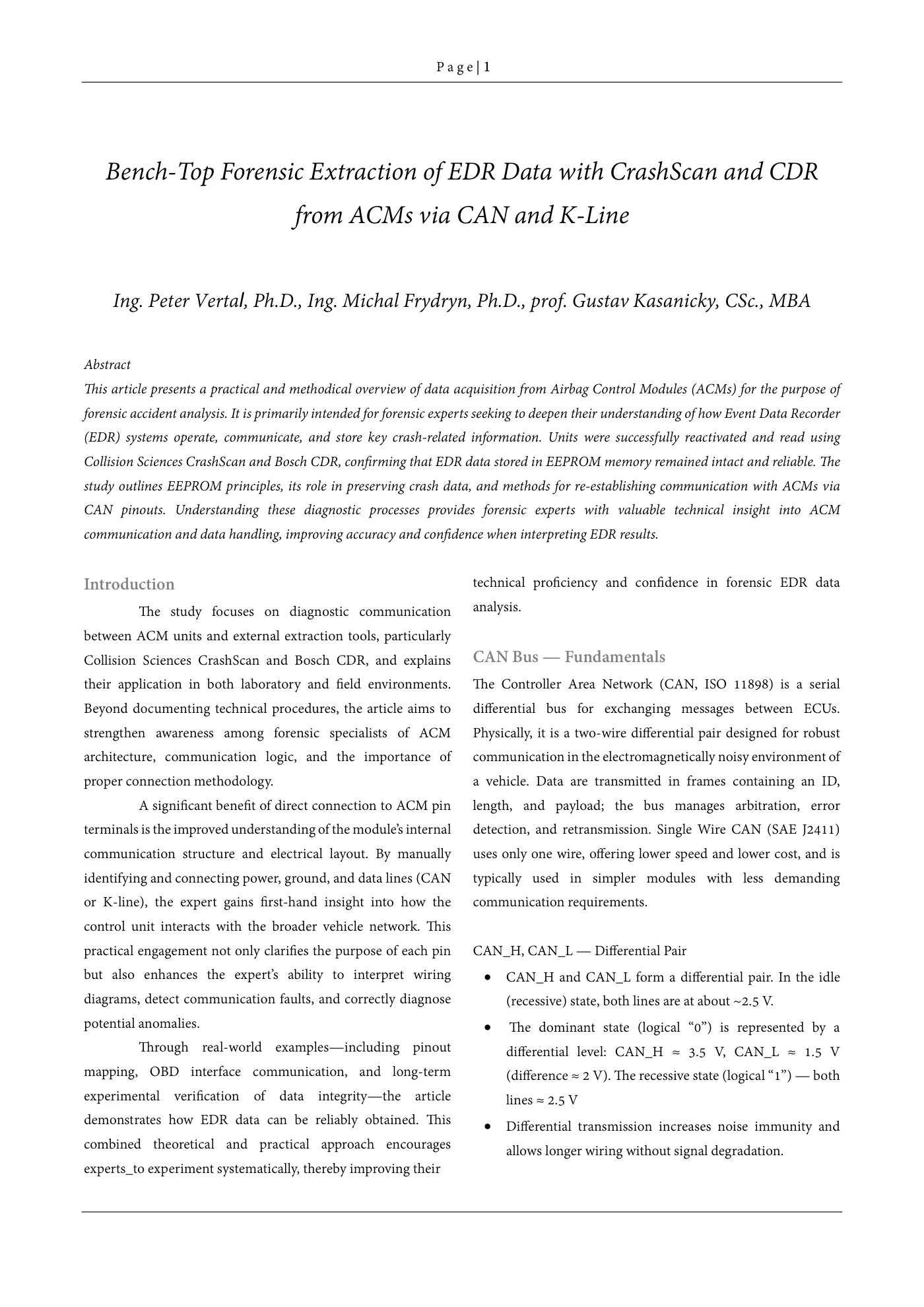
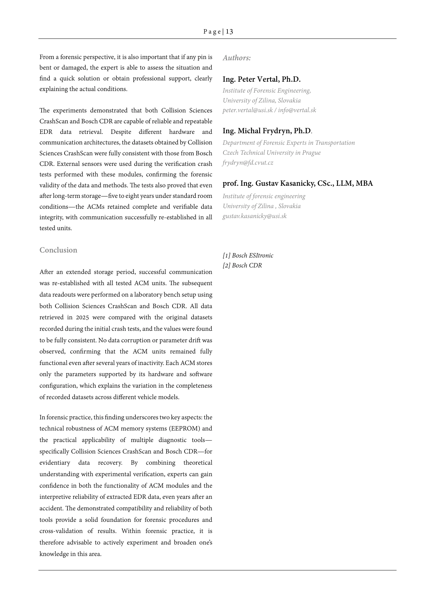
The connector interface of an Airbag Control Module (ACM) is typically divided into several distinct pin sections. These sections are physically separated by solid internal walls inside the connector housing, ensuring mechanical stability and preventing incorrect cable insertion. Each section contains a specific group of signal or power pins that correspond to different communication or activation circuits within the module. For example, the ACM used in the Toyota Auris features three separate pin areas, which are conventionally labeled as A, B, and C. This standardized labeling helps technicians and forensic analysts quickly identify connection points and ensures reliable and repeatable linking between the ACM and diagnostic tools such as CrashScan and CDR.
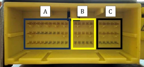
Figure 1 Illustrative view of the pin layout
The illustration shows the connector layout of an Airbag Control Module (ACM) with a structured pin distribution divided into three separate sections, labeled A, B, and C. Each section contains a defined number of terminals used for specific signal, power, and communication lines. The labeling in the diagram defines the numerical identification of the pins, starting from number 1 and continuing sequentially within each designated section. Such numbering is essential during diagnostic procedures and subsequent testing of the control unit, where precise pin mapping is required for correct connection and data acquisition. This layout ensures proper orientation and prevents incorrect cable attachment during EDR data retrieval or module testing.
In some cases, this numbering is also printed directly on the ACM housing, while in other instances it is indicated on the dedicated CDR connection cable corresponding to the specific control unit. This dual marking facilitates accurate identification of pin positions and minimizes the risk of incorrect wiring during data extraction or diagnostic procedures.
08 / In this resource
Data acquisition with Collision Sciences CrashScan
Event Data Recorder (EDR) data stored in Airbag Control Modules (ACMs) were extracted using the CrashScan application and the EDRlab Kit. This setup allows stable and repeatable bench-top data acquisition after the ACM is removed from the vehicle, though in-vehicle retrieval is also supported. Network termination is achieved with a 60 Ω or 120 Ω resistor, depending on the bus topology. The OBD Breakout Cable with color-coded wires simplifies direct connection to ACMs. Most modules use the 60 Ω version; if communication fails, the 120 Ω cable is applied to match internal termination.
The EDRlab Kit includes all necessary components to establish communication with ACM units. A key advantage of CrashScan bench-top use is that no OEM-specific harnesses are required. The software provides pinout diagrams, and jumper pins ensure correct power, CAN-H/CAN-L, K-line, and ignition connections for reliable forensic data extraction.
Practical forensic demonstration of data acquisition from Toyota Auris – CAN communication
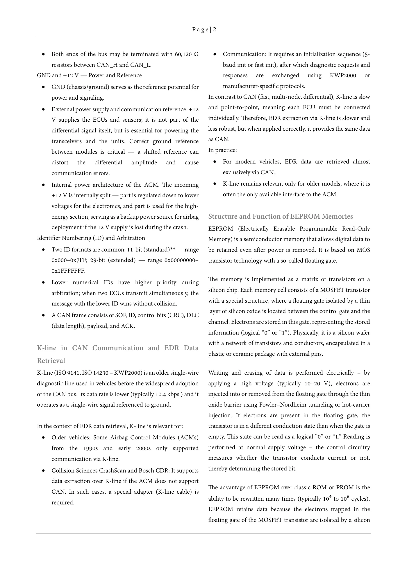
To retrieve data using CrashScan, it is first necessary to determine the pinout configuration of the individual connections to the ACM. After entering the vehicle information—such as manufacturer, model, and year of production—on the Collision Sciences website, the system automatically generates the corresponding wiring scheme for data acquisition. In certain cases, it is also necessary to provide the ACM unit number for precise identification. For example, the Toyota Auris 2014 equipped with a TRW ACM labeled 89170-02B90 required entering this number, which is printed directly on the housing, into the pin connection search field to obtain the correct pinout configuration.
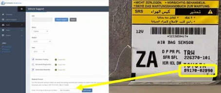
Figure 2 Determine the pinout configuration of Toyota Auris ACM on Collision Sciences website
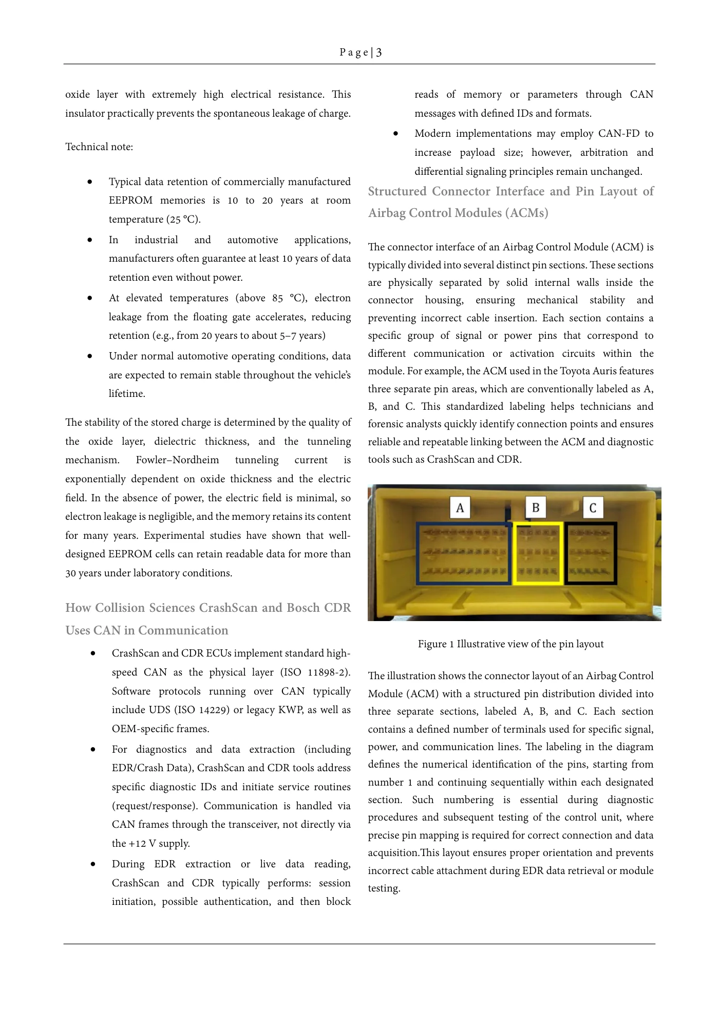
It is a straightforward process, and this specific example applies only to Toyota vehicles. Subsequently, the pinout for the corresponding unit is displayed.
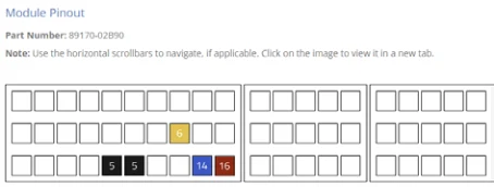
Figure 3 Generated pinout for the Toyota Auris ACM on the Collision Sciences website
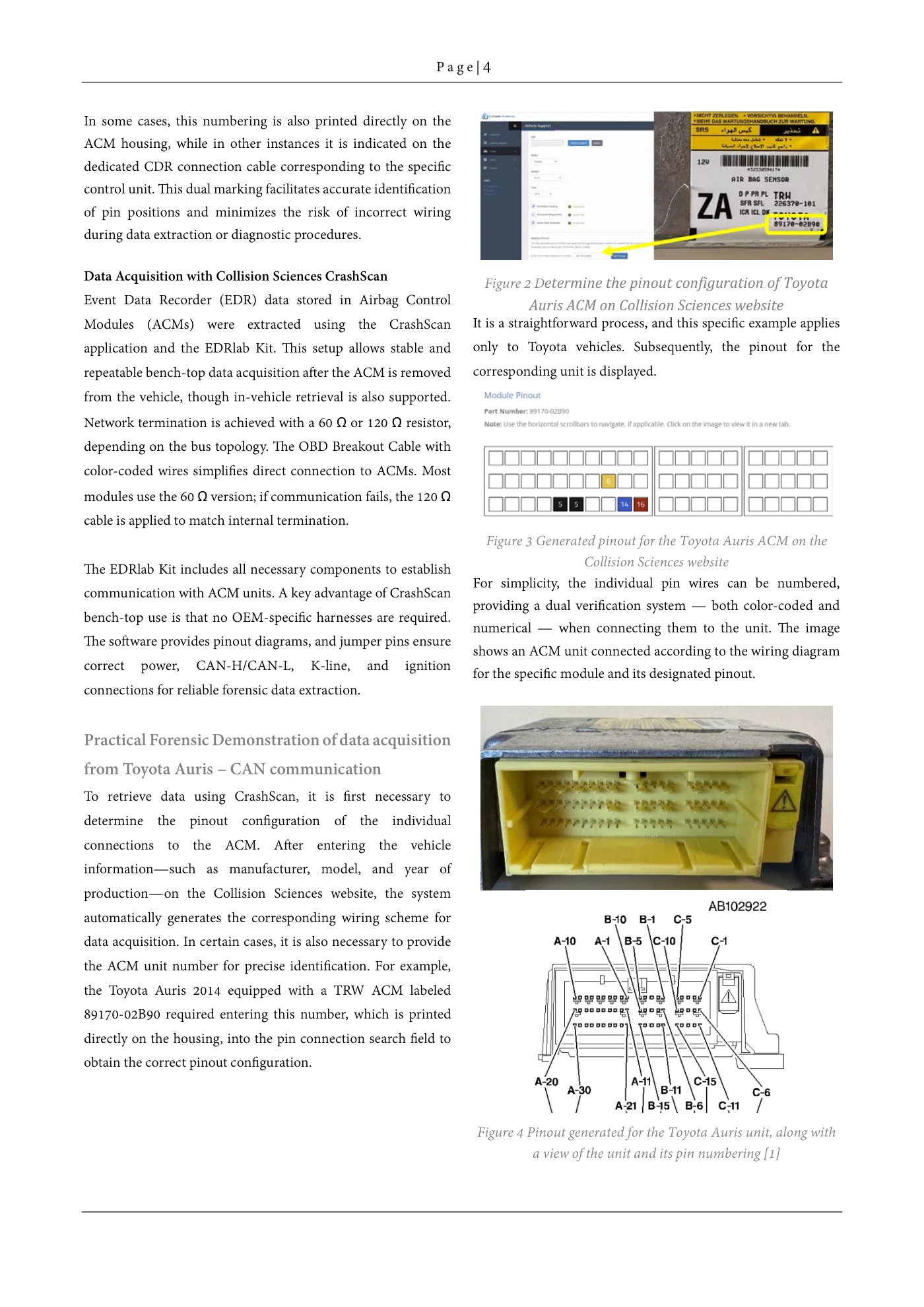
For simplicity, the individual pin wires can be numbered, providing a dual verification system — both color-coded and numerical — when connecting them to the unit. The image shows an ACM unit connected according to the wiring diagram for the specific module and its designated pinout.
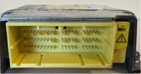
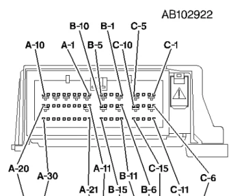
Figure 4 Pinout generated for the Toyota Auris unit, along with a view of the unit and its pin numbering [1]
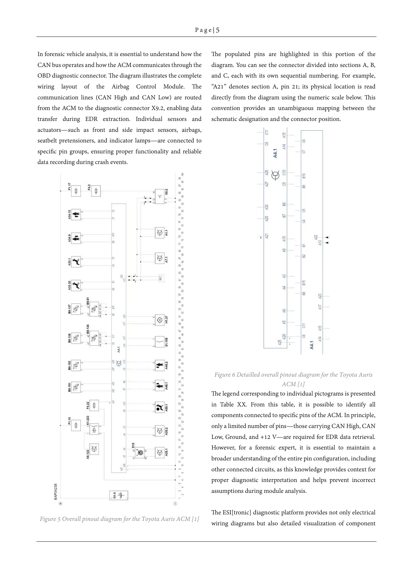
In forensic vehicle analysis, it is essential to understand how the CAN bus operates and how the ACM communicates through the OBD diagnostic connector. The diagram illustrates the complete wiring layout of the Airbag Control Module. The communication lines (CAN High and CAN Low) are routed from the ACM to the diagnostic connector X9.2, enabling data transfer during EDR extraction. Individual sensors and actuators—such as front and side impact sensors, airbags, seatbelt pretensioners, and indicator lamps—are connected to specific pin groups, ensuring proper functionality and reliable data recording during crash events.
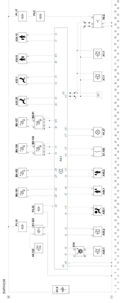
Figure 5 Overall pinout diagram for the Toyota Auris ACM [1]
The populated pins are highlighted in this portion of the diagram. You can see the connector divided into sections A, B, and C, each with its own sequential numbering. For example, “A21” denotes section A, pin 21; its physical location is read directly from the diagram using the numeric scale below. This convention provides an unambiguous mapping between the schematic designation and the connector position.
Figure 6 Detailed overall pinout diagram for the Toyota Auris ACM [1]
The legend corresponding to individual pictograms is presented in Table XX. From this table, it is possible to identify all components connected to specific pins of the ACM. In principle, only a limited number of pins—those carrying CAN High, CAN Low, Ground, and +12 V—are required for EDR data retrieval. However, for a forensic expert, it is essential to maintain a broader understanding of the entire pin configuration, including other connected circuits, as this knowledge provides context for proper diagnostic interpretation and helps prevent incorrect assumptions during module analysis.
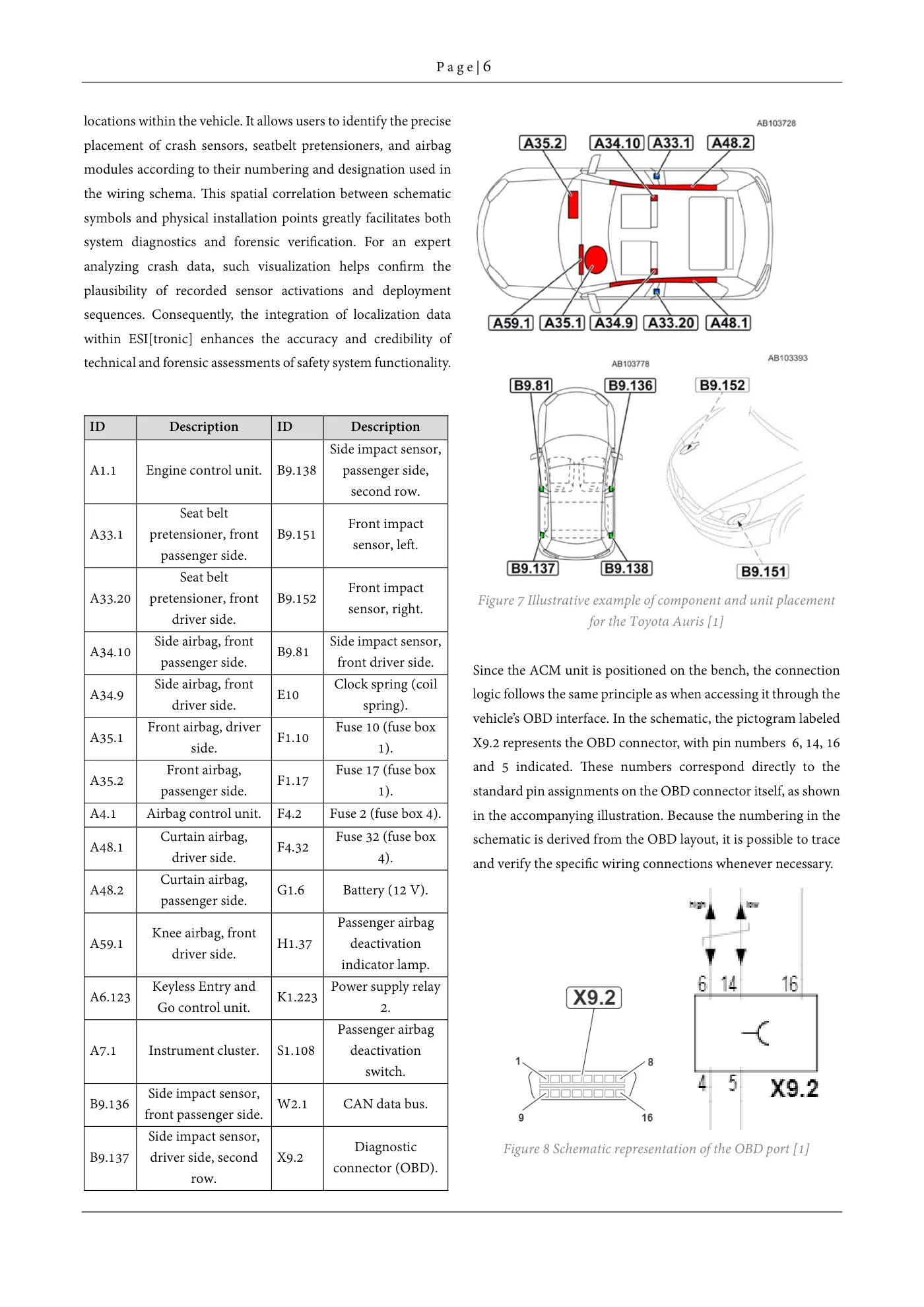
The ESI[tronic] diagnostic platform provides not only electrical wiring diagrams but also detailed visualization of component locations within the vehicle. It allows users to identify the precise placement of crash sensors, seatbelt pretensioners, and airbag modules according to their numbering and designation used in the wiring schema. This spatial correlation between schematic symbols and physical installation points greatly facilitates both system diagnostics and forensic verification. For an expert analyzing crash data, such visualization helps confirm the plausibility of recorded sensor activations and deployment sequences. Consequently, the integration of localization data within ESI[tronic] enhances the accuracy and credibility of technical and forensic assessments of safety system functionality.
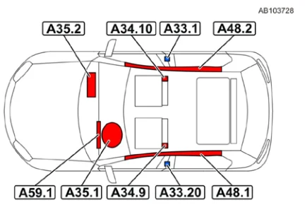
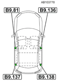
Figure 7 Illustrative example of component and unit placement for the Toyota Auris [1]
Since the ACM unit is positioned on the bench, the connection logic follows the same principle as when accessing it through the vehicle’s OBD interface. In the schematic, the pictogram labeled X9.2 represents the OBD connector, with pin numbers 6, 14, 16 and 5 indicated. These numbers correspond directly to the standard pin assignments on the OBD connector itself, as shown in the accompanying illustration. Because the numbering in the schematic is derived from the OBD layout, it is possible to trace and verify the specific wiring connections whenever necessary.
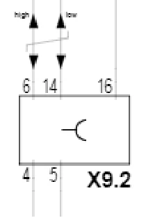
Figure 8 Schematic representation of the OBD port [1]
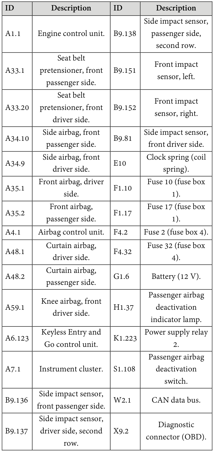
Read extracted table text
The image preserves the original columns. Extracted text below is retained for accessibility; refer to the table image or PDF for row and column relationships.
ID description ID description
A1.1 Engine control unit. B9.138 Side impact sensor, passenger side, second row.
A33.1 Seat belt pretensioner, front passenger side.
B9.151 Front impact sensor, left.
A33.20 Seat belt pretensioner, front driver side.
B9.152 Front impact sensor, right.
A34.10 Side airbag, front passenger side.
B9.81 Side impact sensor, front driver side.
A34.9 Side airbag, front driver side.
E10 Clock spring (coil spring).
A35.1 Front airbag, driver side.
F1.10 Fuse 10 (fuse box 1).
A35.2 Front airbag, passenger side.
F1.17 Fuse 17 (fuse box 1).
A4.1 Airbag control unit. F4.2 Fuse 2 (fuse box 4).
A48.1 Curtain airbag, driver side.
F4.32 Fuse 32 (fuse box 4).
A48.2 Curtain airbag, passenger side.
G1.6 Battery (12 V).
A59.1 Knee airbag, front driver side.
H1.37 Passenger airbag deactivation indicator lamp.
A6.123 Keyless Entry and Go control unit.
K1.223 Power supply relay 2.
A7.1 Instrument cluster. S1.108 Passenger airbag deactivation switch.
B9.136 Side impact sensor, front passenger side. W2.1 CAN data bus.
B9.137 Side impact sensor, driver side, second row.
X9.2 Diagnostic connector (OBD).
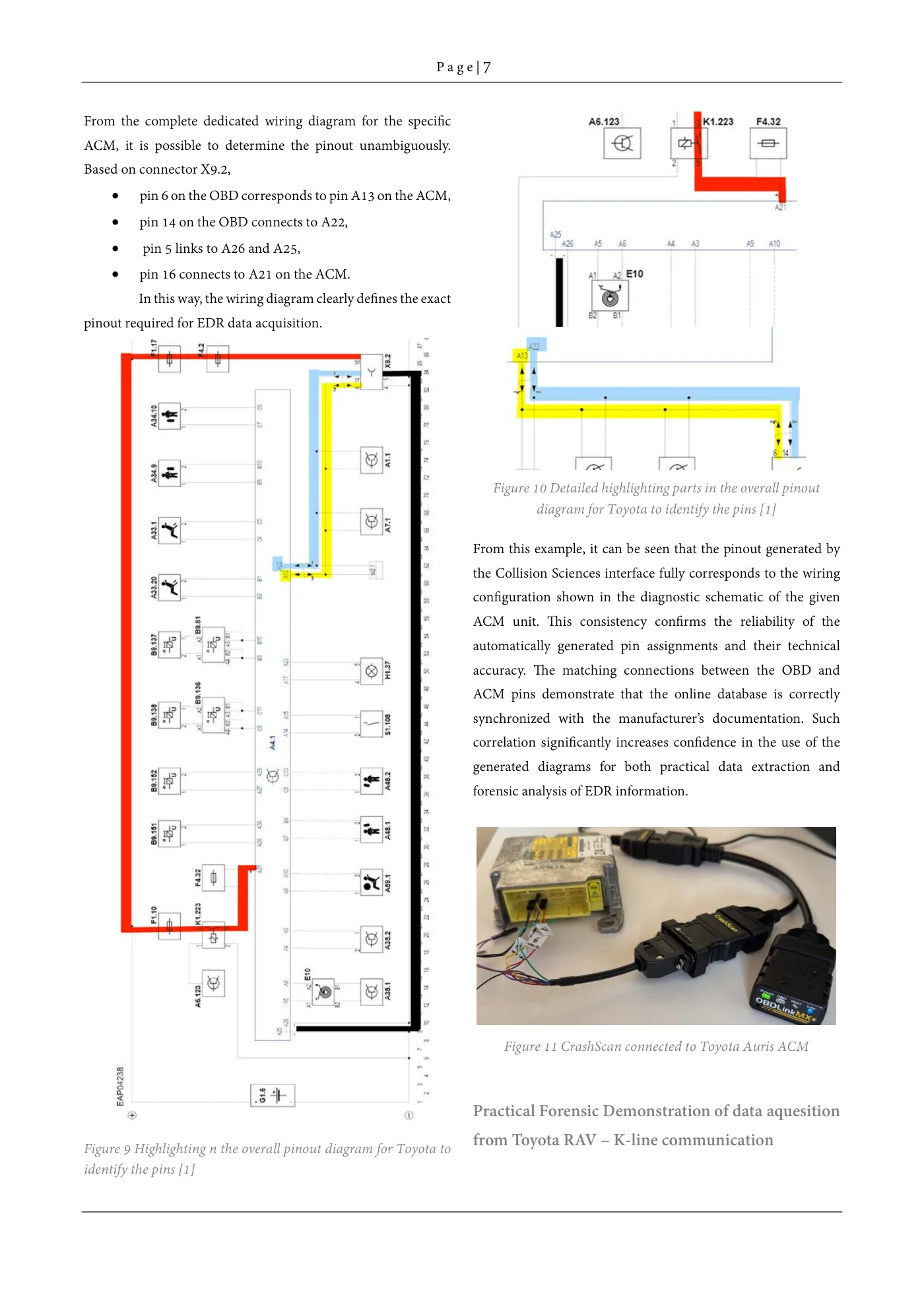
From the complete dedicated wiring diagram for the specific ACM, it is possible to determine the pinout unambiguously. Based on connector X9.2,
- pin 6 on the OBD corresponds to pin A13 on the ACM,
- pin 14 on the OBD connects to A22,
- pin 5 links to A26 and A25,
- pin 16 connects to A21 on the ACM. In this way, the wiring diagram clearly defines the exact pinout required for EDR data acquisition.
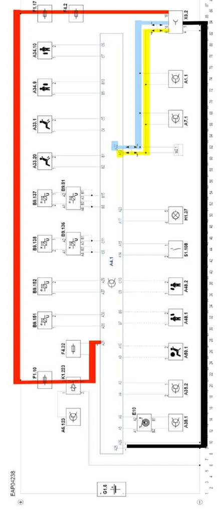
Figure 9 Highlighting n the overall pinout diagram for Toyota to identify the pins [1]
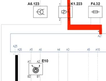
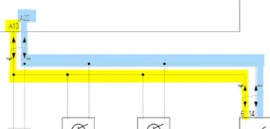
Figure 10 Detailed highlighting parts in the overall pinout diagram for Toyota to identify the pins [1]
From this example, it can be seen that the pinout generated by the Collision Sciences interface fully corresponds to the wiring configuration shown in the diagnostic schematic of the given ACM unit. This consistency confirms the reliability of the automatically generated pin assignments and their technical accuracy. The matching connections between the OBD and ACM pins demonstrate that the online database is correctly synchronized with the manufacturer’s documentation. Such correlation significantly increases confidence in the use of the generated diagrams for both practical data extraction and forensic analysis of EDR information.
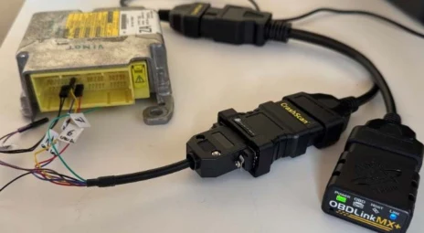
Figure 11 CrashScan connected to Toyota Auris ACM
Practical forensic demonstration of data acquisition from Toyota RAV – K-line communication
Some older modules and control units may communicate via the K-line interface. In such cases, it is not necessary to connect the CAN High and CAN Low lines, as communication occurs solely over the K-line. When this configuration applies (89170-42201) , it is immediately apparent from the generated pinout how the unit should be connected.
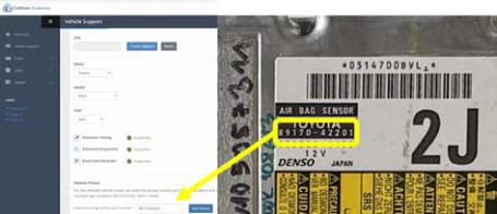
Figure 12 Determine the pinout configuration of Toyota RAV4 ACM
Based on the input parameters, the web interface automatically generated the wiring diagram. The scheme was tailored specifically to the selected Toyota RAV4 model and production year. This ensured accurate identification of the correct pin connections for data acquisition.
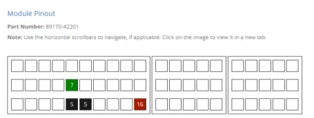
Figure 13 Generated pinout for the RAV4 ACM on the Collision Sciences website.
The connection procedure is defined in a precise and unambiguous manner. Each step follows a standardized sequence that eliminates uncertainty during setup. As a result, the risk of wiring or communication errors is practically excluded.
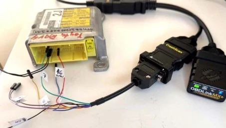
Figure 14 CrashScan connected to Toyota RAV4 ACM
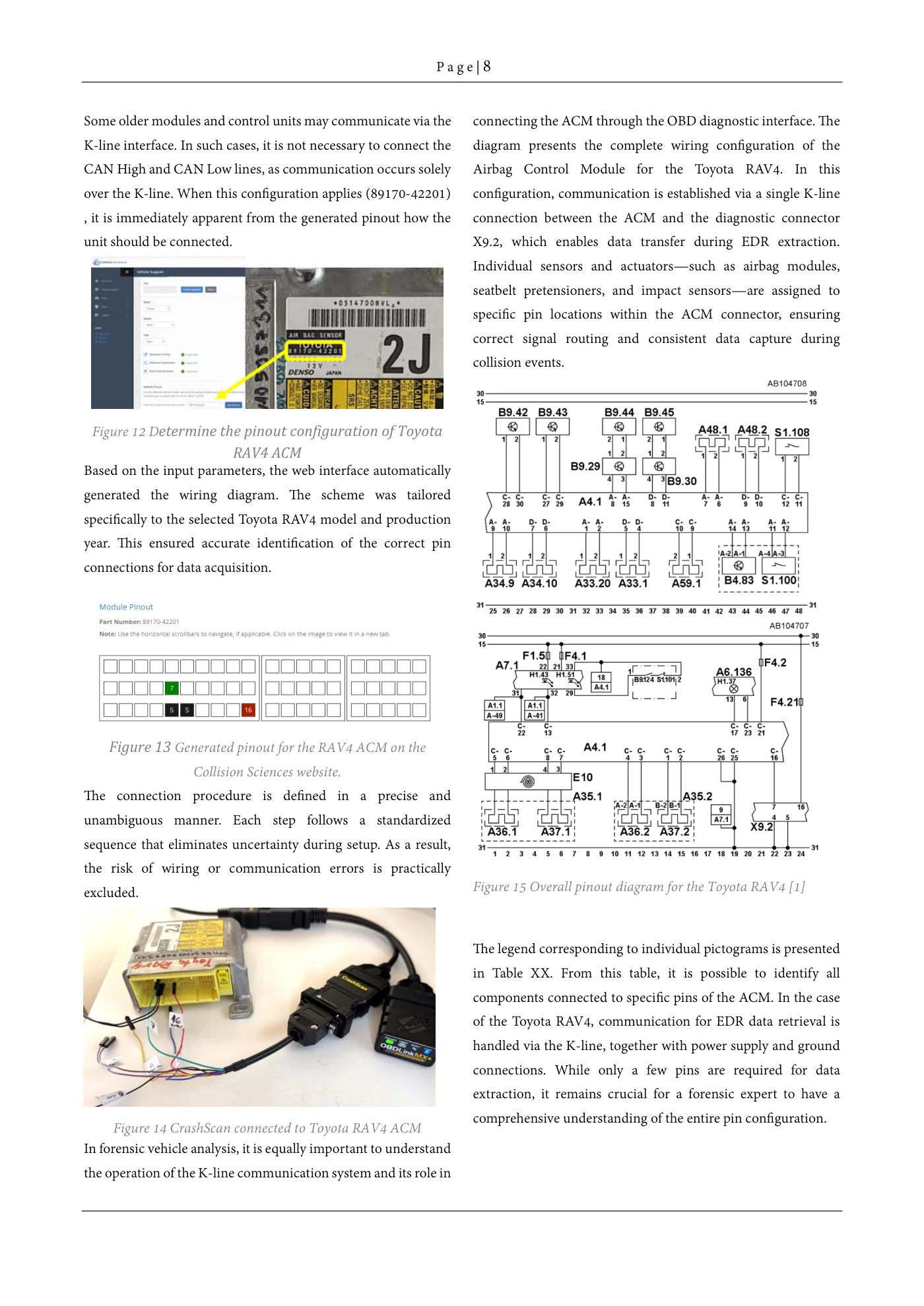
In forensic vehicle analysis, it is equally important to understand the operation of the K-line communication system and its role in connecting the ACM through the OBD diagnostic interface. The diagram presents the complete wiring configuration of the Airbag Control Module for the Toyota RAV4. In this configuration, communication is established via a single K-line connection between the ACM and the diagnostic connector X9.2, which enables data transfer during EDR extraction. Individual sensors and actuators—such as airbag modules, seatbelt pretensioners, and impact sensors—are assigned to specific pin locations within the ACM connector, ensuring correct signal routing and consistent data capture during collision events.
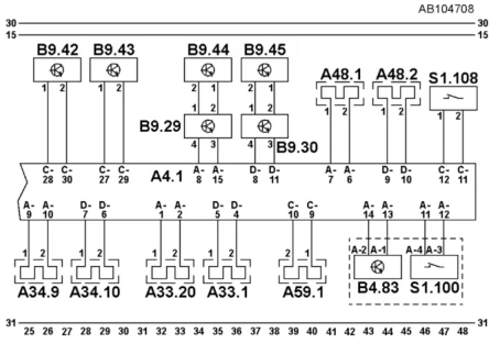
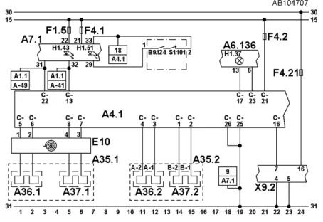
Figure 15 Overall pinout diagram for the Toyota RAV4 [1]
The legend corresponding to individual pictograms is presented in Table XX. From this table, it is possible to identify all components connected to specific pins of the ACM. In the case of the Toyota RAV4, communication for EDR data retrieval is handled via the K-line, together with power supply and ground connections. While only a few pins are required for data extraction, it remains crucial for a forensic expert to have a comprehensive understanding of the entire pin configuration.
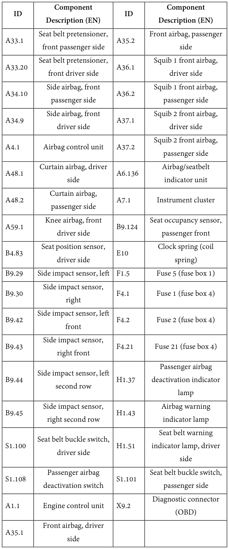
Read extracted table text
The image preserves the original columns. Extracted text below is retained for accessibility; refer to the table image or PDF for row and column relationships.
ID component
Description (en) ID component
Description (en)
A33.1 Seat belt pretensioner, front passenger side A35.2 Front airbag, passenger side
A33.20 Seat belt pretensioner, front driver side A36.1 Squib 1 front airbag, driver side
A34.10 Side airbag, front passenger side A36.2 Squib 1 front airbag, passenger side
A34.9 Side airbag, front driver side A37.1 Squib 2 front airbag, driver side
A4.1 Airbag control unit A37.2 Squib 2 front airbag, passenger side
A48.1 Curtain airbag, driver side A6.136 Airbag/seatbelt indicator unit
A48.2 Curtain airbag, passenger side A7.1 Instrument cluster
A59.1 Knee airbag, front driver side B9.124 Seat occupancy sensor, passenger front
B4.83 Seat position sensor, driver side E10 Clock spring (coil spring) B9.29 Side impact sensor, left F1.5 Fuse 5 (fuse box 1)
B9.30 Side impact sensor, right F4.1 Fuse 1 (fuse box 4)
B9.42 Side impact sensor, left front F4.2 Fuse 2 (fuse box 4)
B9.43 Side impact sensor, right front F4.21 Fuse 21 (fuse box 4)
B9.44 Side impact sensor, left second row H1.37 Passenger airbag deactivation indicator lamp
B9.45 Side impact sensor, right second row H1.43 Airbag warning indicator lamp
S1.100 Seat belt buckle switch, driver side H1.51 Seat belt warning indicator lamp, driver side
S1.108 Passenger airbag deactivation switch S1.101 Seat belt buckle switch, passenger side
A1.1 Engine control unit X9.2 Diagnostic connector (OBD)
A35.1 Front airbag, driver side
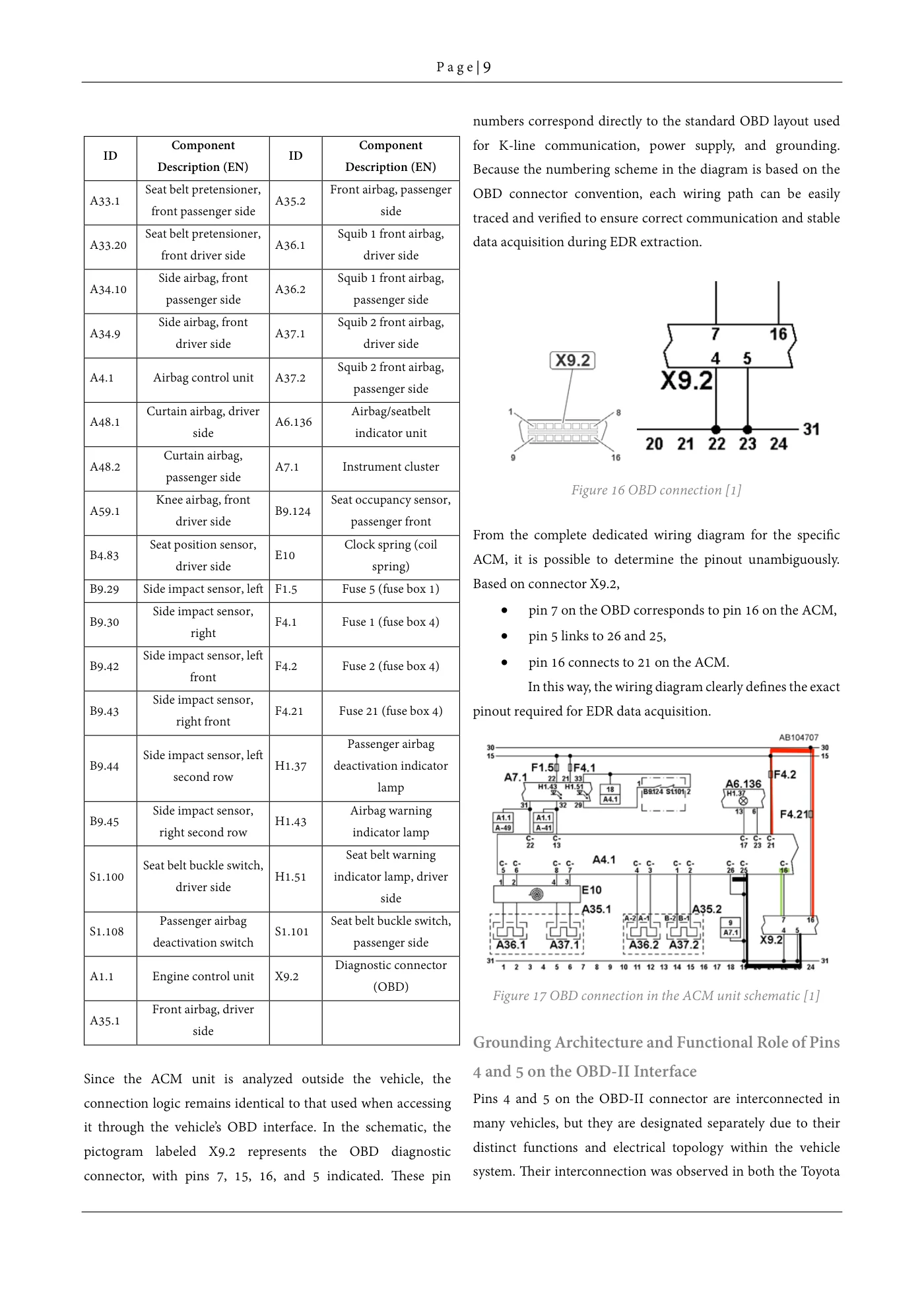
Since the ACM unit is analyzed outside the vehicle, the connection logic remains identical to that used when accessing it through the vehicle’s OBD interface. In the schematic, the pictogram labeled X9.2 represents the OBD diagnostic connector, with pins 7, 15, 16, and 5 indicated. These pin numbers correspond directly to the standard OBD layout used for K-line communication, power supply, and grounding. Because the numbering scheme in the diagram is based on the OBD connector convention, each wiring path can be easily traced and verified to ensure correct communication and stable data acquisition during EDR extraction.
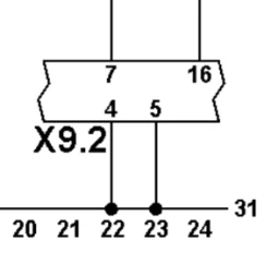
Figure 16 OBD connection [1]
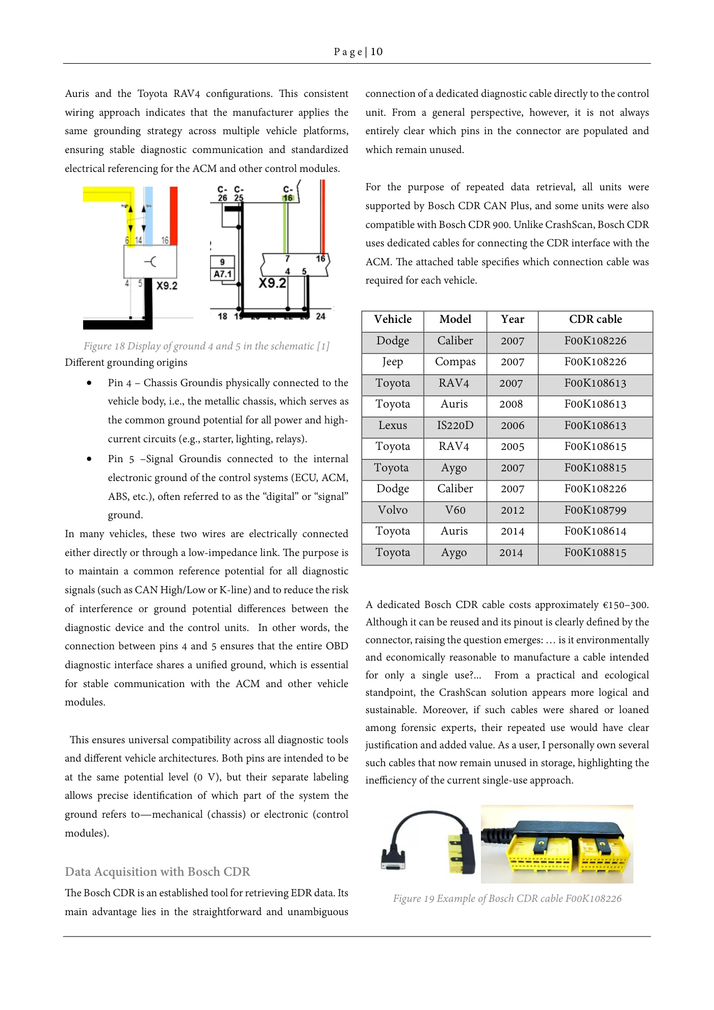
From the complete dedicated wiring diagram for the specific ACM, it is possible to determine the pinout unambiguously. Based on connector X9.2,
- pin 7 on the OBD corresponds to pin 16 on the ACM,
- pin 5 links to 26 and 25,
- pin 16 connects to 21 on the ACM. In this way, the wiring diagram clearly defines the exact pinout required for EDR data acquisition.
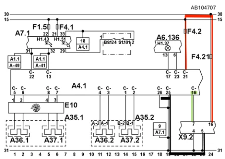
Figure 17 OBD connection in the ACM unit schematic [1]
Grounding architecture and functional role of pins 4 and 5 on the OBD-II interface
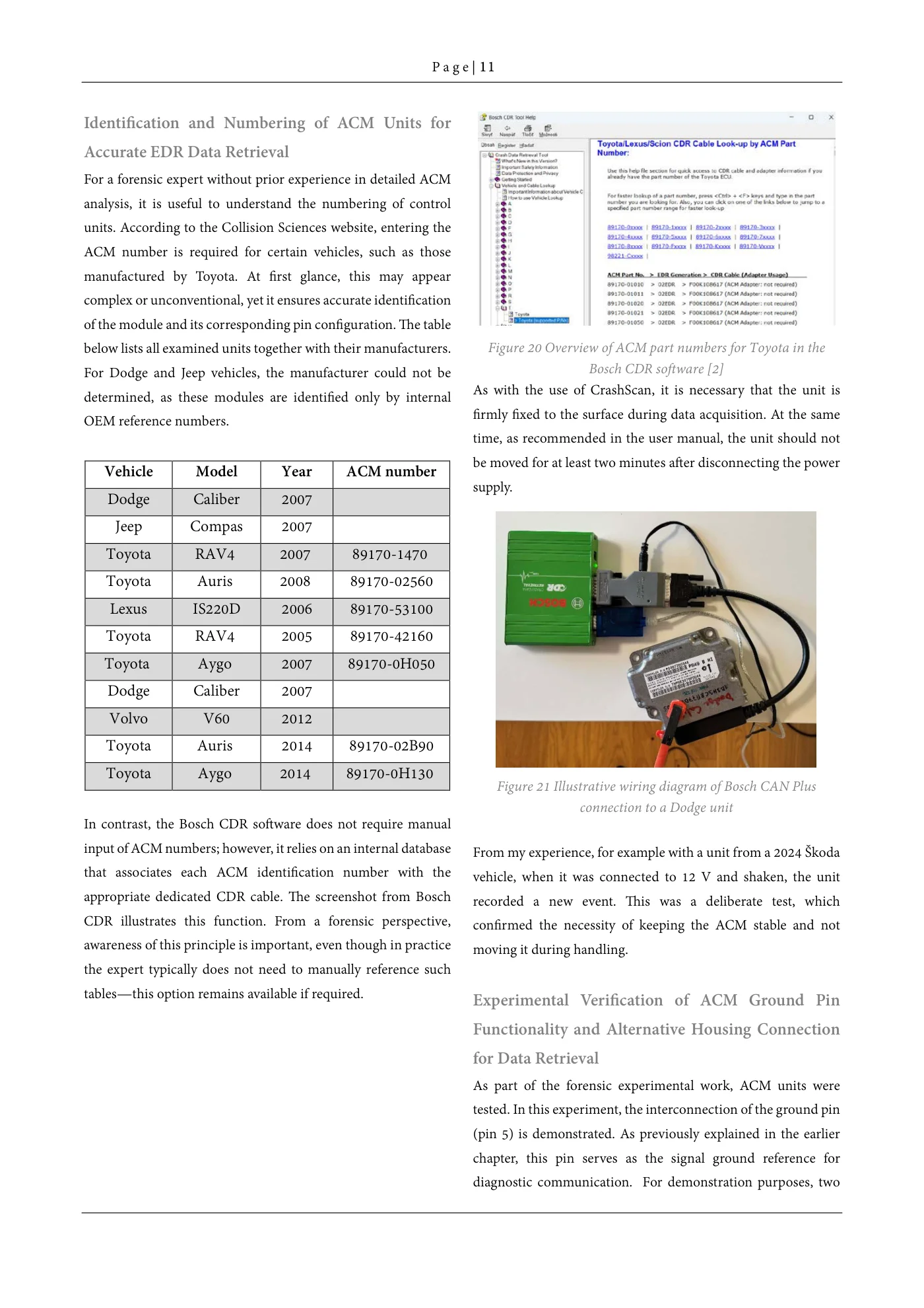
Pins 4 and 5 on the OBD-II connector are interconnected in many vehicles, but they are designated separately due to their distinct functions and electrical topology within the vehicle system. Their interconnection was observed in both the Toyota Auris and the Toyota RAV4 configurations. This consistent wiring approach indicates that the manufacturer applies the same grounding strategy across multiple vehicle platforms, ensuring stable diagnostic communication and standardized electrical referencing for the ACM and other control modules.
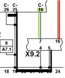
Figure 18 Display of ground 4 and 5 in the schematic [1]
Different grounding origins
- Pin 4 – Chassis Ground is physically connected to the vehicle body, i.e., the metallic chassis, which serves as the common ground potential for all power and high-current circuits (e.g., starter, lighting, relays).
- Pin 5 – Signal Ground is connected to the internal electronic ground of the control systems (ECU, ACM, ABS, etc.), often referred to as the “digital” or “signal” ground. In many vehicles, these two wires are electrically connected either directly or through a low-impedance link. The purpose is to maintain a common reference potential for all diagnostic signals (such as CAN High/Low or K-line) and to reduce the risk of interference or ground potential differences between the diagnostic device and the control units. In other words, the connection between pins 4 and 5 ensures that the entire OBD diagnostic interface shares a unified ground, which is essential for stable communication with the ACM and other vehicle modules.
This ensures universal compatibility across all diagnostic tools and different vehicle architectures. Both pins are intended to be at the same potential level (0 V), but their separate labeling allows precise identification of which part of the system the ground refers to—mechanical (chassis) or electronic (control modules).
09 / In this resource
Data acquisition with Bosch CDR
The Bosch CDR is an established tool for retrieving EDR data. Its main advantage lies in the straightforward and unambiguous connection of a dedicated diagnostic cable directly to the control unit. From a general perspective, however, it is not always entirely clear which pins in the connector are populated and which remain unused.
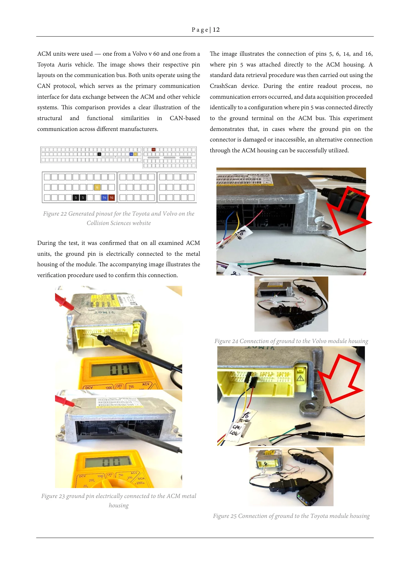
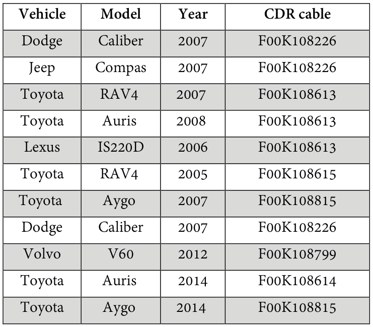
For the purpose of repeated data retrieval, all units were supported by Bosch CDR CAN Plus, and some units were also compatible with Bosch CDR 900. Unlike CrashScan, Bosch CDR uses dedicated cables for connecting the CDR interface with the ACM. The attached table specifies which connection cable was required for each vehicle.
Read extracted table text
The image preserves the original columns. Extracted text below is retained for accessibility; refer to the table image or PDF for row and column relationships.
Vehicle model year CDR cable Dodge Caliber 2007 f00k108226 Jeep Compas 2007 f00k108226 Toyota RAV4 2007 f00k108613 Toyota Auris 2008 f00k108613 Lexus is220d 2006 f00k108613 Toyota RAV4 2005 f00k108615 Toyota Aygo 2007 f00k108815 Dodge Caliber 2007 f00k108226 Volvo v60 2012 f00k108799 Toyota Auris 2014 f00k108614 Toyota Aygo 2014 f00k108815
A dedicated Bosch CDR cable costs approximately €150–300. Although it can be reused and its pinout is clearly defined by the connector, raising the question emerges: … is it environmentally and economically reasonable to manufacture a cable intended for only a single use?... From a practical and ecological standpoint, the CrashScan solution appears more logical and sustainable. Moreover, if such cables were shared or loaned among forensic experts, their repeated use would have clear justification and added value. As a user, I personally own several such cables that now remain unused in storage, highlighting the inefficiency of the current single-use approach.
Figure 19 Example of Bosch CDR cable F00K108226
10 / In this resource
Identification and numbering of ACM units for accurate EDR data retrieval
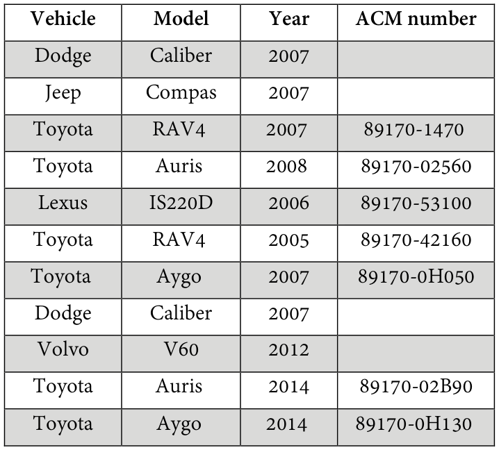
For a forensic expert without prior experience in detailed ACM analysis, it is useful to understand the numbering of control units. According to the Collision Sciences website, entering the ACM number is required for certain vehicles, such as those manufactured by Toyota. At first glance, this may appear complex or unconventional, yet it ensures accurate identification of the module and its corresponding pin configuration. The table below lists all examined units together with their manufacturers. For Dodge and Jeep vehicles, the manufacturer could not be determined, as these modules are identified only by internal OEM reference numbers.
Read extracted table text
The image preserves the original columns. Extracted text below is retained for accessibility; refer to the table image or PDF for row and column relationships.
Vehicle model year ACM number Dodge Caliber 2007 Jeep Compas 2007 Toyota RAV4 2007 89170-1470 Toyota Auris 2008 89170-02560 Lexus is220d 2006 89170-53100 Toyota RAV4 2005 89170-42160 Toyota Aygo 2007 89170-0h050 Dodge Caliber 2007 Volvo v60 2012 Toyota Auris 2014 89170-02b90 Toyota Aygo 2014 89170-0h130
In contrast, the Bosch CDR software does not require manual input of ACM numbers; however, it relies on an internal database that associates each ACM identification number with the appropriate dedicated CDR cable. The screenshot from Bosch CDR illustrates this function. From a forensic perspective, awareness of this principle is important, even though in practice the expert typically does not need to manually reference such tables—this option remains available if required.
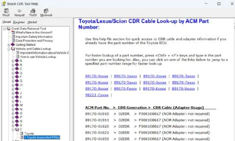
Figure 20 Overview of ACM part numbers for Toyota in the Bosch CDR software [2]
As with the use of CrashScan, it is necessary that the unit is firmly fixed to the surface during data acquisition. At the same time, as recommended in the user manual, the unit should not be moved for at least two minutes after disconnecting the power supply.
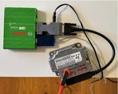
Figure 21 Illustrative wiring diagram of Bosch CAN Plus connection to a Dodge unit
From my experience, for example with a unit from a 2024 Škoda vehicle, when it was connected to 12 V and shaken, the unit recorded a new event. This was a deliberate test, which confirmed the necessity of keeping the ACM stable and not moving it during handling.
11 / In this resource
Experimental verification of ACM ground pin functionality and alternative housing connection for data retrieval
As part of the forensic experimental work, ACM units were tested. In this experiment, the interconnection of the ground pin (pin 5) is demonstrated. As previously explained in the earlier chapter, this pin serves as the signal ground reference for diagnostic communication. For demonstration purposes, two ACM units were used — one from a Volvo v 60 and one from a Toyota Auris vehicle. The image shows their respective pin layouts on the communication bus. Both units operate using the CAN protocol, which serves as the primary communication interface for data exchange between the ACM and other vehicle systems. This comparison provides a clear illustration of the structural and functional similarities in CAN-based communication across different manufacturers.
Figure 22 Generated pinout for the Toyota and Volvo on the Collision Sciences website
During the test, it was confirmed that on all examined ACM units, the ground pin is electrically connected to the metal housing of the module. The accompanying image illustrates the verification procedure used to confirm this connection.
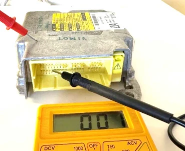
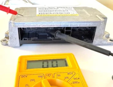
Figure 23 ground pin electrically connected to the ACM metal housing
The image illustrates the connection of pins 5, 6, 14, and 16, where pin 5 was attached directly to the ACM housing. A standard data retrieval procedure was then carried out using the CrashScan device. During the entire readout process, no communication errors occurred, and data acquisition proceeded identically to a configuration where pin 5 was connected directly to the ground terminal on the ACM bus. This experiment demonstrates that, in cases where the ground pin on the connector is damaged or inaccessible, an alternative connection through the ACM housing can be successfully utilized.
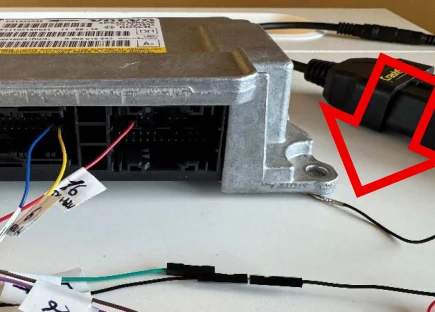
Figure 24 Connection of ground to the Volvo module housing
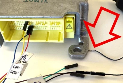
Figure 25 Connection of ground to the Toyota module housing
From a forensic perspective, it is also important that if any pin is bent or damaged, the expert is able to assess the situation and find a quick solution or obtain professional support, clearly explaining the actual conditions.
The experiments demonstrated that both Collision Sciences CrashScan and Bosch CDR are capable of reliable and repeatable EDR data retrieval. Despite different hardware and communication architectures, the datasets obtained by Collision Sciences CrashScan were fully consistent with those from Bosch CDR. External sensors were used during the verification crash tests performed with these modules, confirming the forensic validity of the data and methods. The tests also proved that even after long-term storage—five to eight years under standard room conditions—the ACMs retained complete and verifiable data integrity, with communication successfully re-established in all tested units.
12 / In this resource
Conclusion
After an extended storage period, successful communication was re-established with all tested ACM units. The subsequent data readouts were performed on a laboratory bench setup using both Collision Sciences CrashScan and Bosch CDR. All data retrieved in 2025 were compared with the original datasets recorded during the initial crash tests, and the values were found to be fully consistent. No data corruption or parameter drift was observed, confirming that the ACM units remained fully functional even after several years of inactivity. Each ACM stores only the parameters supported by its hardware and software configuration, which explains the variation in the completeness of recorded datasets across different vehicle models.
In forensic practice, this finding underscores two key aspects: the technical robustness of ACM memory systems (EEPROM) and the practical applicability of multiple diagnostic tools— specifically Collision Sciences CrashScan and Bosch CDR—for evidentiary data recovery. By combining theoretical understanding with experimental verification, experts can gain confidence in both the functionality of ACM modules and the interpretive reliability of extracted EDR data, even years after an accident. The demonstrated compatibility and reliability of both tools provide a solid foundation for forensic procedures and cross-validation of results. Within forensic practice, it is therefore advisable to actively experiment and broaden one’s knowledge in this area.
13 / In this resource
Authors:
Ing. Peter Vertal, Ph.D.
Institute of Forensic Engineering, University of Zilina, Slovakia peter.vertal@usi.sk / info@vertal.sk
Ing. Michal Frydryn, Ph.D.
Department of Forensic Experts in Transportation Czech Technical University in Prague frydryn@fd.cvut.cz
prof. Ing. Gustav Kasanicky, CSc., LLM, MBA
Institute of forensic engineering University of Zilina , Slovakia gustav.kasanicky@usi.sk
[1] Bosch ESItronic [2] Bosch CDR