
Read page 1 text
CRASHSCAN - COLLISION SCIENCES Inc EDR data retrieval system COMPARATIVE ANALYSIS, RELIABILITY AND TECHNICAL CHARACTERISTICS Requesting party: Guardia Civil Traffic Division (Spain) Date: April 2026 Author: EDR Europe Solutions Team Version 1.0
Read page 2 text
EDR Europe SL - C.I.F: B02716520 Tel: 828 027 557 ? E-mail: info@edr-europe.eu Page 2 Contents 1. INTRODUCTION ....................................................................................................... 3 2. CRASHSCAN SYSTEM ............................................................................................ 5 2.1. SYSTEM ARCHITECTURE ......................................................................................... 5 2.2. COMMUNICATION WITH THE VEHICLE ................................................................. 8 2.3. NATURE OF TRANSMITTED DATA AND TECHNICAL PROCESSING ................... 9 2.4. INFORMATION SECURITY IN TRANSIT AND AT REST ......................................... 11 2.4.1. PROTECTION DURING TRANSMISSION ........................................................... 11 2.4.2. STORAGE PROTECTION ..................................................................................... 11 2.4.3. LOGICAL SEPARATION OF CLIENTS OR ORGANIZATIONS ............................ 11 2.5. CONTROL OF ACCESS TO REPORTS AND LINKS ................................................ 12 2.6. INTEGRITY, TRACEABILITY AND CHAIN OF CUSTODY ...................................... 12 2.7. INFORMATION RETENTION .................................................................................... 14 2.8. FINAL REPORT CONTENT: DIRECT DATA AND DERIVED / CALCULATED DATA 14 2.9. QUALITY CONTROL AND VALIDATION .................................................................. 15 2.10. FINAL TECHNICAL CONSIDERATIONS ................................................................. 15 3. COMPARATIVE STUDY OF EDR DATA IN A CONTROLLED IMPACT TEST ....... 16 3.1. INTRODUCTION ........................................................................................................ 16 3.2. IDENTIFICATION OF CRASH TEST VEHICLES ...................................................... 17 3.3. IMPACT CONFIGURATION ...................................................................................... 18 3.4. EQUIPMENT USED TO DOCUMENT THE IMPACT TEST ...................................... 19 3.5. EDR SYSTEMS OF THE TESTED VEHICLES .......................................................... 22 3.6. DATA OBTAINED FROM THE DSD INSTRUMENTATION SYSTEM ....................... 23 3.7. COMPARISON CRITERIA USED ............................................................................. 24 3.8. COLLISION SEQUENCE .......................................................................................... 26 3.9. ANALYSIS OF DATA OBTAINED FROM TOYOTA AURIS - P03 ............................. 27 3.10. ANALYSIS OF DATA OBTAINED FROM TOYOTA YARIS - P04 ........................... 29 4. ASSESSMENT OF THE PARAMETERS ANALYZED ............................................. 31 5. FINAL CONSIDERATIONS ..................................................................................... 33 APPENDICES ............................................................................................................ 35 APPENDIX 1: CrashScan Report APPENDIX 2: Bosch Reports APPENDIX 3: Comparative Tables
Read page 3 text
EDR Europe SL - C.I.F: B02716520 Tel: 828 027 557 ? E-mail: info@edr-europe.eu Page 3 1. INTRODUCTION The purpose of this report is to describe the CrashScan remote EDR data retrieval system and to perform a comparative study of its reliability using data obtained from an actual crash test involving instrumented vehicles. The CrashScan system is described on the basis of technical information supplied by Collision Sciences Inc., the owner and developer of this EDR data retrieval tool. The objective is not only to describe its general operation, but also to assess the consistency of the data obtained through CrashScan against other reference sources. For this purpose, a crash test conducted during the annual seminar organized by DSD - Dr. Steffan Datentechnik in Austria is used as a case study. In the 2026 edition, the tests were carried out in collaboration with Collision Sciences Inc., incorporating both independent instrumentation installed in the vehicles and subsequent retrieval of EDR data using Bosch CDR and CrashScan. The tests were conducted on March 30, 2026 and included several impact scenarios, including intersection collisions involving two moving vehicles and a frontal impact of a vehicle against a concrete barrier. Within this series of tests, the present report focuses on Crash Test No. 02, which is described in detail in the following sections. Two vehicles were involved in this test, identified as Toyota Auris P03 and Toyota Yaris P04, both monitored during the test. The analyzed data originate from three principal sources: ? EDR reports retrieved using Bosch CDR; ? EDR reports retrieved using CrashScan; ? data recorded by the independent DSD instrumentation installed in the vehicles.
Read page 4 text
EDR Europe SL - C.I.F: B02716520 Tel: 828 027 557 ? E-mail: info@edr-europe.eu Page 4 The purpose of the analysis is to compare the values reported by Bosch and CrashScan with the data recorded by the test instrumentation, with particular attention to parameters relevant to accident reconstruction, such as change in velocity, recorded accelerations and the temporal consistency of stored events. It should be noted that the comparison is not intended to reproduce exactly the internal recording, filtering and integration algorithms used by the vehicles' EDR modules, but rather to assess the technical correspondence among the different available data sources. In this respect, the DSD instrumentation is used as an external reference for the test, while Bosch CDR and CrashScan are compared as systems for retrieving and interpreting the data stored in the vehicles' electronic modules. Accordingly, this report has two purposes: first, to present the general operation of the CrashScan system in an organized manner and, second, to determine whether data retrieved using CrashScan demonstrate sufficient correspondence with data retrieved using Bosch CDR and with the independent instrumentation used during the crash test.
Read page 5 text
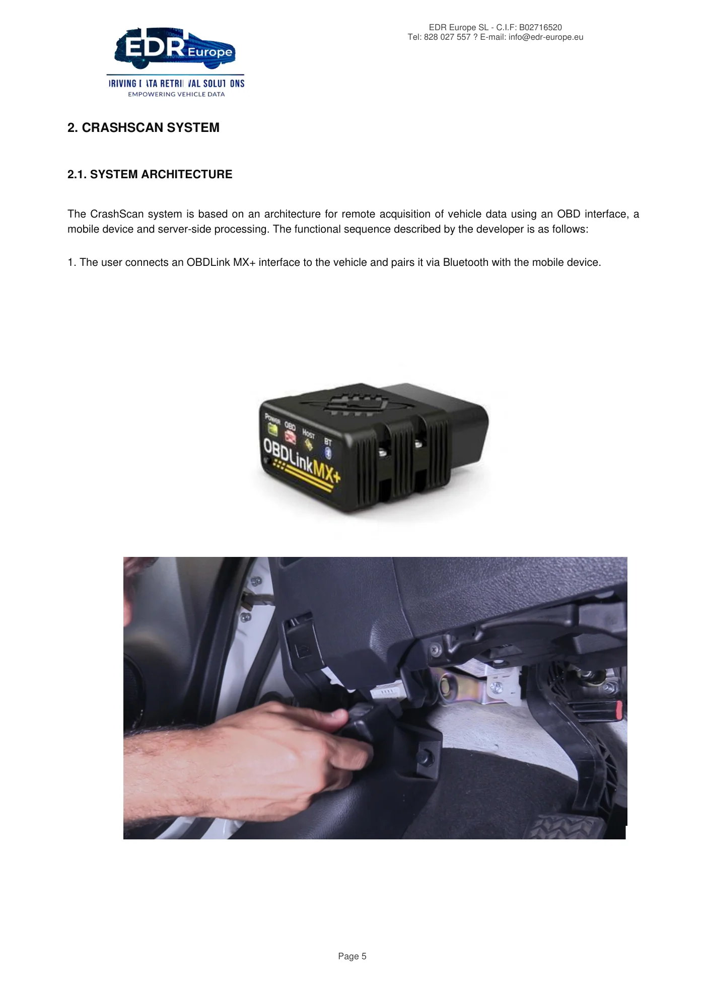
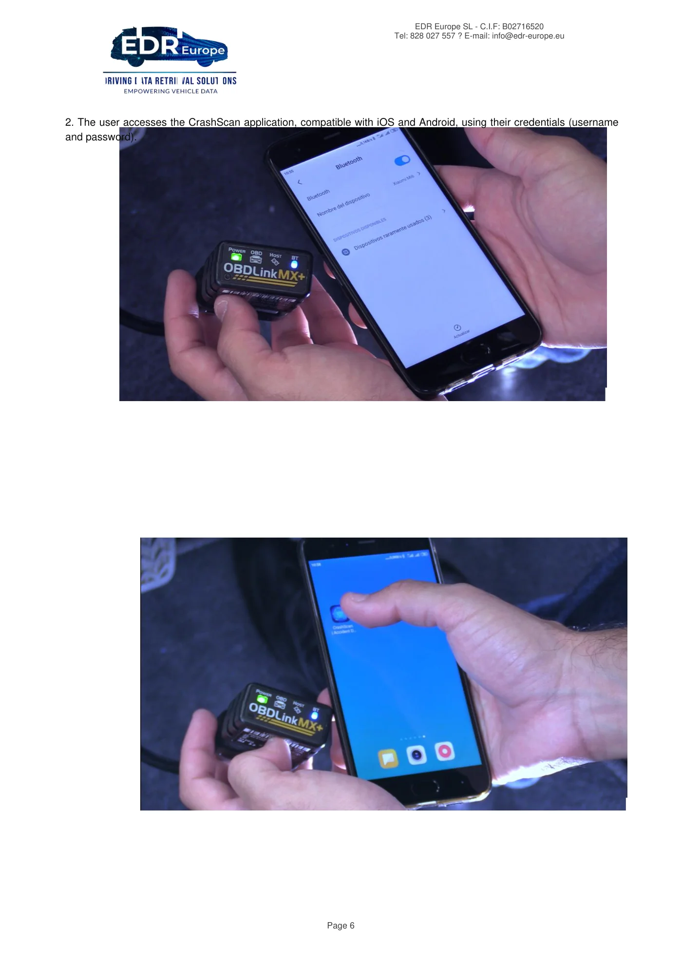
EDR Europe SL - C.I.F: B02716520 Tel: 828 027 557 ? E-mail: info@edr-europe.eu Page 5 2. CRASHSCAN SYSTEM 2.1. SYSTEM ARCHITECTURE The CrashScan system is based on an architecture for remote acquisition of vehicle data using an OBD interface, a mobile device and server-side processing. The functional sequence described by the developer is as follows: 1. The user connects an OBDLink MX+ interface to the vehicle and pairs it via Bluetooth with the mobile device.
Read page 6 text
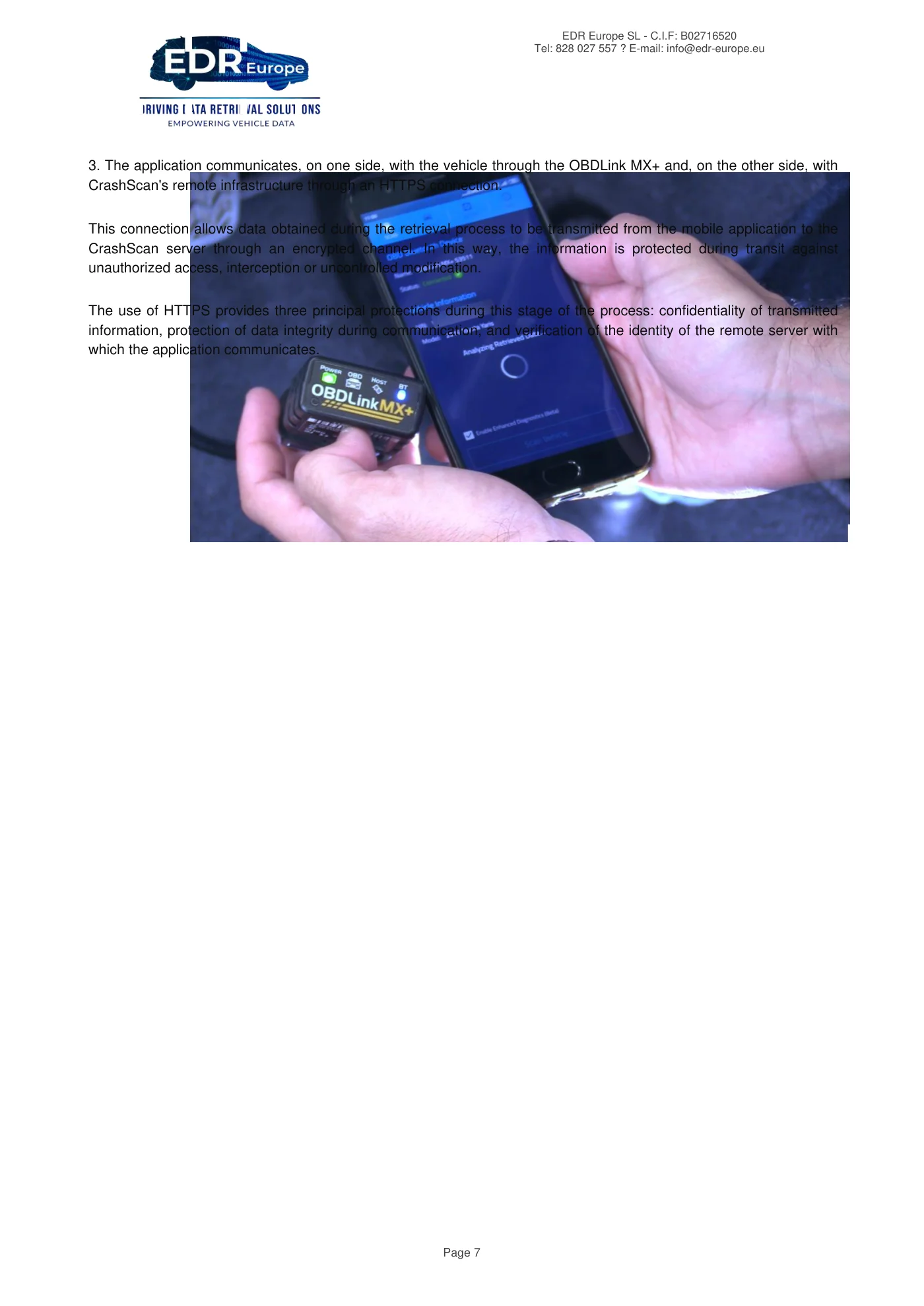
EDR Europe SL - C.I.F: B02716520 Tel: 828 027 557 ? E-mail: info@edr-europe.eu Page 6 2. The user accesses the CrashScan application, compatible with iOS and Android, using their credentials (username and password).
Read page 7 text
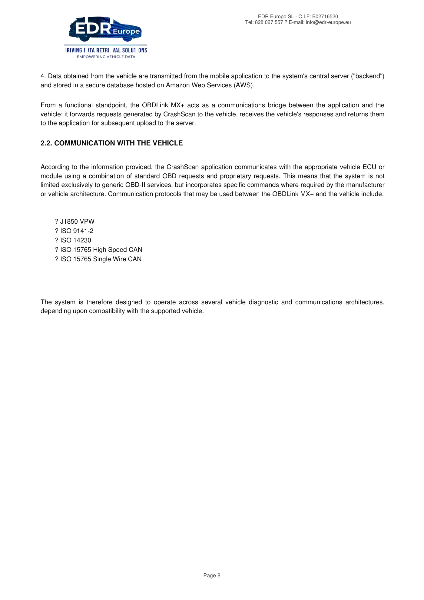
EDR Europe SL - C.I.F: B02716520 Tel: 828 027 557 ? E-mail: info@edr-europe.eu Page 7 3. The application communicates, on one side, with the vehicle through the OBDLink MX+ and, on the other side, with CrashScan's remote infrastructure through an HTTPS connection. This connection allows data obtained during the retrieval process to be transmitted from the mobile application to the CrashScan server through an encrypted channel. In this way, the information is protected during transit against unauthorized access, interception or uncontrolled modification. The use of HTTPS provides three principal protections during this stage of the process: confidentiality of transmitted information, protection of data integrity during communication, and verification of the identity of the remote server with which the application communicates.
Read page 8 text
EDR Europe SL - C.I.F: B02716520 Tel: 828 027 557 ? E-mail: info@edr-europe.eu Page 8 4. Data obtained from the vehicle are transmitted from the mobile application to the system's central server ("backend") and stored in a secure database hosted on Amazon Web Services (AWS). From a functional standpoint, the OBDLink MX+ acts as a communications bridge between the application and the vehicle: it forwards requests generated by CrashScan to the vehicle, receives the vehicle's responses and returns them to the application for subsequent upload to the server. 2.2. COMMUNICATION WITH THE VEHICLE According to the information provided, the CrashScan application communicates with the appropriate vehicle ECU or module using a combination of standard OBD requests and proprietary requests. This means that the system is not limited exclusively to generic OBD-II services, but incorporates specific commands where required by the manufacturer or vehicle architecture. Communication protocols that may be used between the OBDLink MX+ and the vehicle include: ? J1850 VPW ? ISO 9141-2 ? ISO 14230 ? ISO 15765 High Speed CAN ? ISO 15765 Single Wire CAN The system is therefore designed to operate across several vehicle diagnostic and communications architectures, depending upon compatibility with the supported vehicle.
Read page 9 text
EDR Europe SL - C.I.F: B02716520 Tel: 828 027 557 ? E-mail: info@edr-europe.eu Page 9 2.3. NATURE OF TRANSMITTED DATA AND TECHNICAL PROCESSING According to information supplied by Collision Sciences, after a retrieval is performed, the application transmits to the backend not only the vehicle data in raw hexadecimal format, but also metadata associated with the acquisition process and technical error or operating logs. The system therefore retains both primary information originating directly from the vehicle and supplementary information that provides context regarding the retrieval and documents possible technical incidents during the process. Data transmitted from the phone to the backend include: Raw hexadecimal data These are the original responses from the vehicle exactly as produced by its electronic modules, represented in hexadecimal format. ? This is the most fundamental level of the data. ? It is the source from which the report is subsequently generated. Metadata These are data about the retrieval itself, rather than necessarily EDR content. They may include: ? date and time of acquisition, ? user who performed the retrieval, ? device used, ? associated vehicle or session, ? application or system version, ? contextual information concerning the download. These data are used to document the acquisition process and provide traceability.
Read page 10 text
EDR Europe SL - C.I.F: B02716520 Tel: 828 027 557 ? E-mail: info@edr-europe.eu Page 10 Error records or logs These are technical records relating to the retrieval process. They may indicate, for example: ? communication failure, ? incomplete response, ? retry attempts, ? adapter issues, ? problems during connection or upload. These records are not crash data themselves, but they assist in determining how the retrieval process occurred and whether technical problems were encountered. In summary: ? raw data preserve the original information received from the vehicle; ? metadata provide context regarding who performed the retrieval, when it was performed and how it was performed; ? logs allow examination of whether technical incidents occurred during the process. With respect to data processing, it is stated that only minimal processing takes place on the mobile device, primarily to verify that the received responses are complete. All remaining processing occurs on the server side. Collision Sciences further states that the original raw data are retained exactly as acquired from the vehicle module and that these hexadecimal data are available for each supported retrieval and can be supplied upon request. The user can therefore distinguish between primary data acquisition, storage of those data and subsequent analytical interpretation.
Read page 11 text
EDR Europe SL - C.I.F: B02716520 Tel: 828 027 557 ? E-mail: info@edr-europe.eu Page 11 2.4. INFORMATION SECURITY IN TRANSIT AND AT REST 2.4.1. PROTECTION DURING TRANSMISSION Collision Sciences states that communication between the mobile application and the system's remote infrastructure is performed using HTTPS with TLS 1.3. This means that the data travel through a secure encrypted connection, reducing the risk of interception or alteration during transmission. TLS 1.3 is a modern version of the security protocol used for these communications and is designed to provide a high level of protection during data transmission. 2.4.2. STORAGE PROTECTION Collision Sciences states that stored data are maintained in AWS infrastructure and protected using AES-256 encryption. Once stored, the information is protected by an encryption system intended to prevent unauthorized access. AES-256 is an encryption standard widely used in technology and security environments and is considered a robust measure for protecting stored information. 2.4.3. LOGICAL SEPARATION OF CLIENTS OR ORGANIZATIONS Collision Sciences states that customer data are logically separated by organization. Each user is associated with an organization when their account is created, and this forms the mechanism used for internal segregation among different clients or user organizations. This logical separation limits access to data to the appropriate organization and prevents cross-visibility between different users or organizations.
Read page 12 text
EDR Europe SL - C.I.F: B02716520 Tel: 828 027 557 ? E-mail: info@edr-europe.eu Page 12 2.5. CONTROL OF ACCESS TO REPORTS AND LINKS Collision Sciences states that report access links are token based. A validation code is incorporated into the link itself and serves as an access-control mechanism for the document. The links also have a limited period of validity and automatically expire after a defined period. Collision Sciences distinguishes between two situations: ? For preview links, a user must authenticate before gaining access, and the system restricts data visibility to users belonging to the same organization. ? For links to a final report, if the link is shared with third parties, no additional measure prevents those third parties from accessing the report. Responsibility for dissemination therefore rests with the user who shares the link. It is also stated that once a link has been issued, it cannot be manually revoked and remains available until it expires automatically under the normal operation of the system. 2.6. INTEGRITY, TRACEABILITY AND CHAIN OF CUSTODY Collision Sciences states that the system maintains an audit trail or audit log. This internal record identifies when the retrieval was performed, which user performed it, which device was used and when the report was generated. According to the provider, this record serves as the mechanism used to document retrieval traceability and contribute to the chain of custody for data obtained remotely. Collision Sciences also states, however, that the system does not generate specific cryptographic integrity-control mechanisms such as a hash, checksum or digital signature for the uploaded data.

Read page 13 text
EDR Europe SL - C.I.F: B02716520 Tel: 828 027 557 ? E-mail: info@edr-europe.eu Page 13 In other words, a separate mathematical digital fingerprint is not applied to the file or dataset that would subsequently allow independent verification that its contents had not been altered. Accordingly, based upon the information provided, data integrity and traceability are supported by the following elements: ? secure data transmission through HTTPS/TLS 1.3; ? preservation of the original raw data retrieved from the vehicle; ? an audit record linked to the user, the device used, the time of retrieval and the time at which the report was generated.
Read page 14 text
EDR Europe SL - C.I.F: B02716520 Tel: 828 027 557 ? E-mail: info@edr-europe.eu Page 14 2.7. INFORMATION RETENTION Collision Sciences states that it does not delete or remove uploaded data, generated reports or associated logs. From an operational perspective, this represents an indefinite information-retention policy, which can provide advantages for historical review, repetition of analysis or technical support. 2.8. FINAL REPORT CONTENT: DIRECT DATA AND DERIVED / CALCULATED DATA Collision Sciences states that some elements of the final report are taken directly from data recorded by the vehicle, while other elements are calculated by its system, and that derived elements are identified as such in the report. Collision Sciences also states that technical clarification is available upon customer request. With respect to the distinction between raw EDR data and analytically derived or calculated content, Collision Sciences refers to the same clarification. For calculated or derived quantities such as deceleration, braking level, distance to impact, severity classification or Principal Direction of Force (PDOF), CrashScan does not provide formulas, thresholds or calculation assumptions in the documentation reviewed for this report. Instead, Collision Sciences indicates that specific questions should be submitted individually by email. The same response applies to the availability of reviewable technical documentation regarding formulas, assumptions and thresholds. For purposes of a rigorous technical report, this means that: ? the platform does distinguish between recorded information and calculated results; ? the supplied documentation does not describe in detail the mathematical models or exact criteria applied to every derived parameter; ? these matters should therefore be regarded as requiring additional clarification from the manufacturer when relevant to a particular investigation.
Read page 15 text
EDR Europe SL - C.I.F: B02716520 Tel: 828 027 557 ? E-mail: info@edr-europe.eu Page 15 2.9. QUALITY CONTROL AND VALIDATION Collision Sciences maintains an internal Quality Assurance (QA) team that reviews data before the final report is released to the customer. Regarding external or comparative validation, the provider states that several customers have performed evaluations comparing CrashScan against other EDR data extraction tools and that the results were satisfactory. With respect to controlled testing comparing CrashScan with Bosch CDR, manufacturer-specific tools, direct-to-module retrieval or laboratory extraction methods, the response is substantially the same. Collision Sciences additionally indicates that collaborators have prepared technical papers or articles that may be available for sharing. Regarding repeatability, Collision Sciences explains that repeated retrievals generally produce identical data. It acknowledges, however, that in certain vehicles simply restarting the engine can modify parameters such as "ignition cycle at download," which can result in differences in certain fields. 2.10. FINAL TECHNICAL CONSIDERATIONS Based upon the information provided by Collision Sciences, it can be concluded that the system has a technically defined architecture for remote acquisition of vehicle data, including: ? clearly structured vehicle-to-application-to-server communication; ? transmission protected by HTTPS/TLS 1.3; ? storage in AWS using AES-256 encryption; ? logical segregation by organization; ? preservation of the original raw data; ? basic traceability of user, device, acquisition date and report-generation date.
Read page 16 text
EDR Europe SL - C.I.F: B02716520 Tel: 828 027 557 ? E-mail: info@edr-europe.eu Page 16 3. COMPARATIVE STUDY OF EDR DATA IN A CONTROLLED IMPACT TEST 3.1. INTRODUCTION The crash tests were conducted at the facilities of DSD (Dr. Steffan Datentechnik Ges.m.b.H.) in Austria, where the DSD HyperAcc crash-testing system permits collision testing in accordance with EN1317 and EN12767 standards. A propulsion carriage, or sled, is accelerated by an electric motor until the appropriate test speed is reached. Traction force is transmitted using a cable. The test vehicle is coupled to the carriage, which moves along a guided rail. Shortly before the collision point, the carriage decelerates, causing the vehicle to disengage and continue into the target. Technical specifications of the test area Technical specifications of the test area Total test-site area 25,000 m² Maximum acceleration distance 230 m Drive motor power 1 MW Maximum speed for vehicles up to 1,500 kg 110 km/h Maximum speed for vehicles up to 16,000 kg 80 km/h Maximum speed for vehicles up to 38,000 kg 65 km/h DSD test track location: Brunnern 1, 4622 Eggendorf im Traunkreis, Austria https://maps.app.goo.gl/iPC3ZHC5aYdsVP716
Read page 17 text
EDR Europe SL - C.I.F: B02716520 Tel: 828 027 557 ? E-mail: info@edr-europe.eu Page 17 3.2. IDENTIFICATION OF THE CRASH TEST VEHICLES The test used as the reference for this report is Test No. 02, from the series of crash tests conducted on March 30, 2026. The vehicles used and their characteristics are: Field P03 P04 Unit Identification P03 P04 - Make Toyota Toyota - Model Auris 1.4 Yaris 1.0 - Year 2008 2011 - Speed 75 25 km/h Weight 1304 966 kg Length 4.22 3.79 m Width 1.76 1.70 m Height 1.52 1.53 m Wheelbase 2.60 2.46 m Track width 1.53 1.48 m Front axle load 828 593 kg Rear axle load 476 373 kg CG distance to front axle 0.95 0.95 m ECU generation 02EDR 02EDR The remaining crash tests are intended to be analyzed in later versions of this document.
Read page 18 text
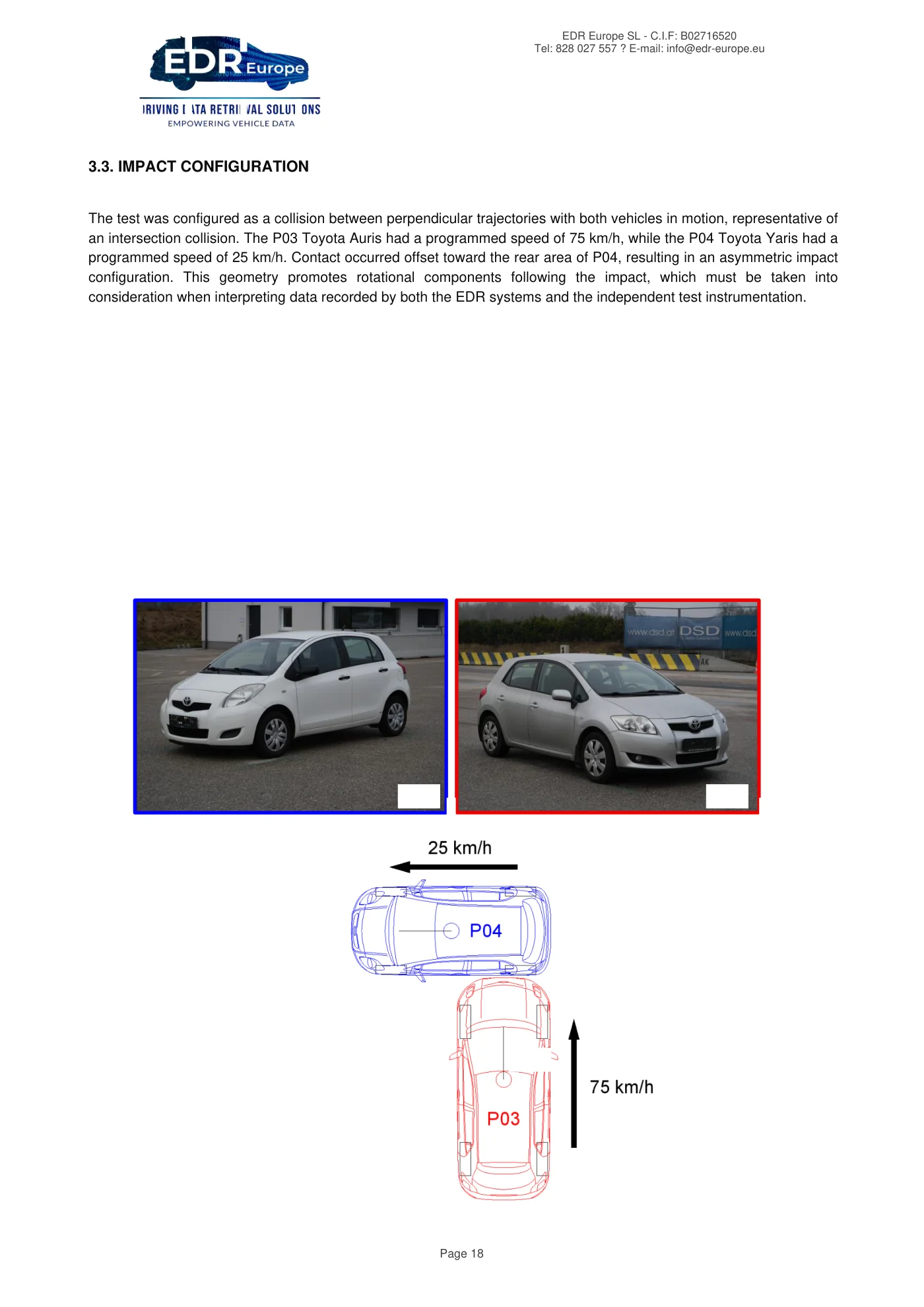
EDR Europe SL - C.I.F: B02716520 Tel: 828 027 557 ? E-mail: info@edr-europe.eu Page 18 3.3. IMPACT CONFIGURATION The test was configured as a collision between perpendicular trajectories with both vehicles in motion, representative of an intersection collision. The P03 Toyota Auris had a programmed speed of 75 km/h, while the P04 Toyota Yaris had a programmed speed of 25 km/h. Contact occurred offset toward the rear area of P04, resulting in an asymmetric impact configuration. This geometry promotes rotational components following the impact, which must be taken into consideration when interpreting data recorded by both the EDR systems and the independent test instrumentation.
Read page 19 text
EDR Europe SL - C.I.F: B02716520 Tel: 828 027 557 ? E-mail: info@edr-europe.eu Page 19 3.4. EQUIPMENT USED TO DOCUMENT THE IMPACT TEST The equipment used by DSD was as follows: Measurement instrumentation ? DSD RPiDaq ? GPS ? Accelerometer (x, y, z) ? Angular velocity (x, y, z) Video ? High-speed cameras ? Standard-speed cameras EDR data retrieval systems ? Collision Sciences - CrashScan ? Bosch CDR
Read page 20 text
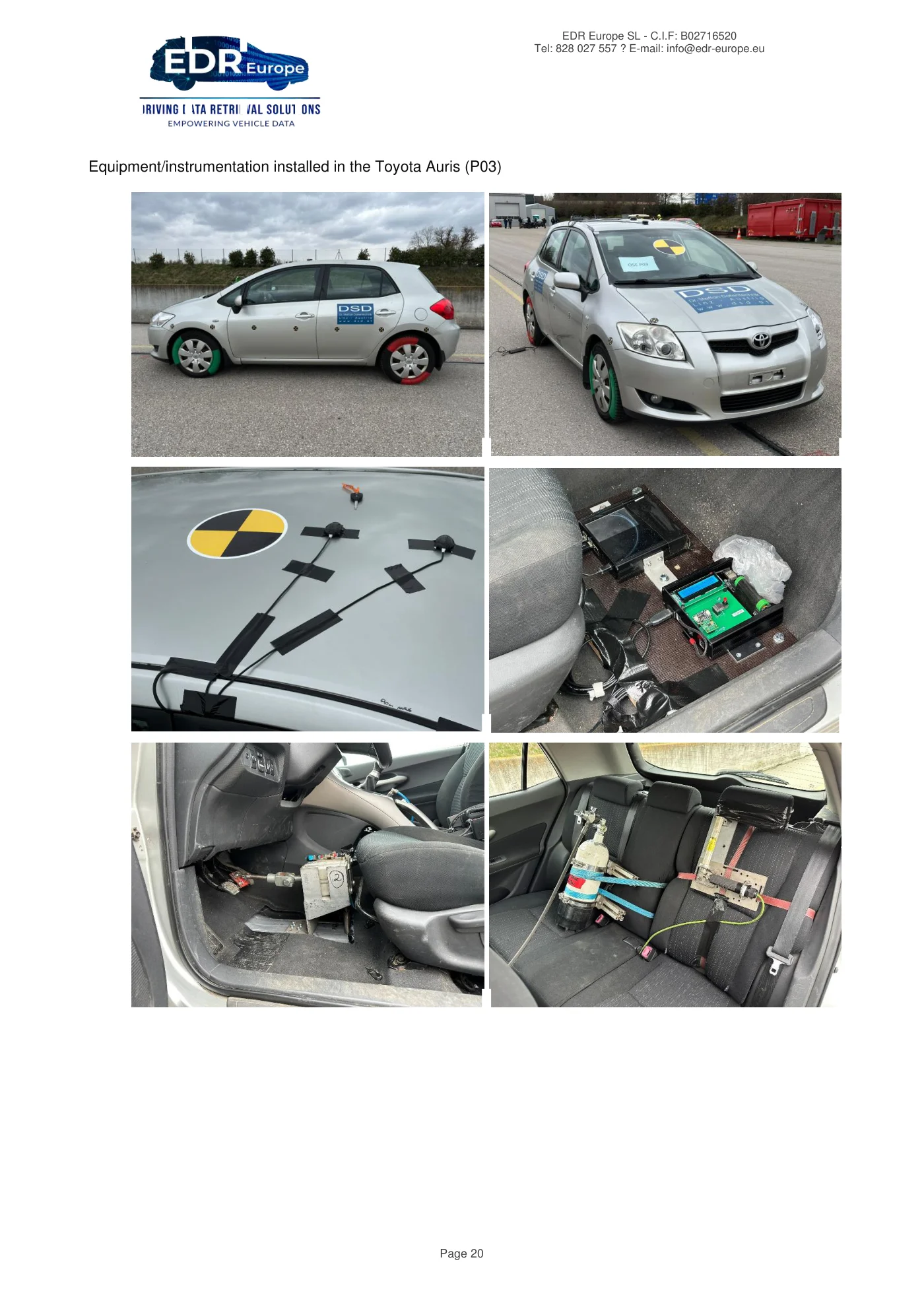
EDR Europe SL - C.I.F: B02716520 Tel: 828 027 557 ? E-mail: info@edr-europe.eu Page 20 Equipment/instrumentation installed in the Toyota Auris (P03)
Read page 21 text
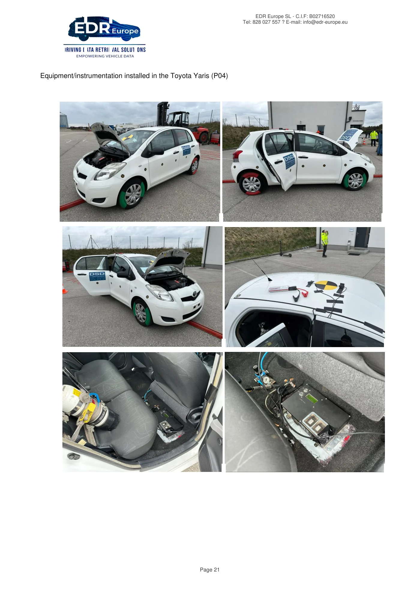
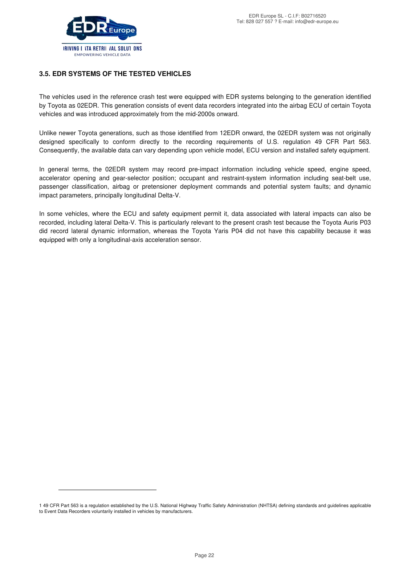
EDR Europe SL - C.I.F: B02716520 Tel: 828 027 557 ? E-mail: info@edr-europe.eu Page 21 Equipment/instrumentation installed in the Toyota Yaris (P04)
Read page 22 text
EDR Europe SL - C.I.F: B02716520 Tel: 828 027 557 ? E-mail: info@edr-europe.eu Page 22 3.5. EDR SYSTEMS OF THE TESTED VEHICLES The vehicles used in the reference crash test were equipped with EDR systems belonging to the generation identified by Toyota as 02EDR. This generation consists of event data recorders integrated into the airbag ECU of certain Toyota vehicles and was introduced approximately from the mid-2000s onward. Unlike newer Toyota generations, such as those identified from 12EDR onward, the 02EDR system was not originally designed specifically to conform directly to the recording requirements of U.S. regulation 49 CFR Part 563. Consequently, the available data can vary depending upon vehicle model, ECU version and installed safety equipment. In general terms, the 02EDR system may record pre-impact information including vehicle speed, engine speed, accelerator opening and gear-selector position; occupant and restraint-system information including seat-belt use, passenger classification, airbag or pretensioner deployment commands and potential system faults; and dynamic impact parameters, principally longitudinal Delta-V. In some vehicles, where the ECU and safety equipment permit it, data associated with lateral impacts can also be recorded, including lateral Delta-V. This is particularly relevant to the present crash test because the Toyota Auris P03 did record lateral dynamic information, whereas the Toyota Yaris P04 did not have this capability because it was equipped with only a longitudinal-axis acceleration sensor. 1 49 CFR Part 563 is a regulation established by the U.S. National Highway Traffic Safety Administration (NHTSA) defining standards and guidelines applicable to Event Data Recorders voluntarily installed in vehicles by manufacturers.
Read page 23 text
EDR Europe SL - C.I.F: B02716520 Tel: 828 027 557 ? E-mail: info@edr-europe.eu Page 23 3.6. DATA OBTAINED FROM THE DSD INSTRUMENTATION SYSTEM The test vehicles were equipped with an independent monitoring system installed by DSD that recorded various dynamic parameters during the crash test. From the available information, the parameters of greatest interest for impact reconstruction and comparison against the EDR data retrieved using Bosch CDR and CrashScan were selected: ? Longitudinal velocity. ? Lateral velocity. ? Longitudinal acceleration. ? Lateral acceleration. ? Angular velocity about the vertical axis. The analysis period was centered on the collision-pulse interval because this period is directly related to generation of EDR events and calculation of the changes in velocity experienced by the vehicles. Pre-impact velocity data were also considered because they provide an important reference against which the speeds recorded by the different EDR retrieval systems can be compared. It must be recognized that in this test the vehicles were not travelling under their own propulsion. Instead, they were moved using an external cable-pulling system. Conventional pre-impact parameters such as accelerator position and engine speed are therefore not representative of normal driving conditions. Accordingly, except for pre-impact speed, these parameters have little specific relevance to the purpose of this study.
Read page 24 text
EDR Europe SL - C.I.F: B02716520 Tel: 828 027 557 ? E-mail: info@edr-europe.eu Page 24 3.7. COMPARISON CRITERIA USED A consistent comparison methodology was used based upon three sources of information: ? EDR reports retrieved using Bosch CDR. ? EDR reports retrieved using CrashScan. ? Data recorded by DSD instrumentation installed in the vehicles during the crash test. Values from Bosch CDR and CrashScan were taken directly from the EDR reports generated by the respective systems. These data represent information recorded by the vehicle's electronic modules and subsequently presented by each retrieval tool. The DSD data were used as an external reference because they were generated by independent instrumentation specifically installed to measure vehicle dynamics during the test. The comparison was performed separately for each vehicle, considering the available and relevant parameters in each case. Both pre-impact information and information associated with the collision pulse were considered. For the pre-impact phase, DSD velocity records were compared against the pre-crash speeds shown in the EDR reports. This allows assessment of the consistency between the speed measured by independent instrumentation and the speed recorded by the vehicle's electronic modules before the event. For the collision pulse, a general comparison window of t = 0 ms to t = 150 ms was used for comparison against the DSD data. This common time window provides a reference for comparing the principal evolution of the impact against the Delta-V values reported by the EDR systems. However, this analysis window does not necessarily reproduce the internal triggering, integration and storage logic used by the Toyota ACM.
Read page 25 text
EDR Europe SL - C.I.F: B02716520 Tel: 828 027 557 ? E-mail: info@edr-europe.eu Page 25 The module may apply its own criteria to define the beginning of an event, select the calculation window, filter signals or store particular values. Differences between EDR values and values estimated from DSD must therefore be interpreted cautiously within the technical context of the test. For the Toyota Auris P03, a previous TRG 1 event was identified whose timing was inconsistent with the principal impact documented during the crash test. For this reason, that event is considered unrelated to the principal test and is not used as a reference for assessing correspondence among Bosch CDR, CrashScan and DSD. Analysis of the principal collision is centered upon TRG 2 and the associated lateral event. For the Toyota Yaris P04, two Front/Rear events were documented approximately 280 ms apart. This circumstance is considered when interpreting the impact sequence and comparing Bosch CDR, CrashScan and DSD. The two records should not be treated as a single continuous event without first considering their temporal separation. Accordingly, the comparison performed in this report is not intended to reproduce the exact internal EDR recording algorithm. Instead, its objective is to assess the technical consistency between values reported by Bosch CDR and CrashScan and the objective data recorded by the independent instrumentation installed for the crash test.
Read page 26 text
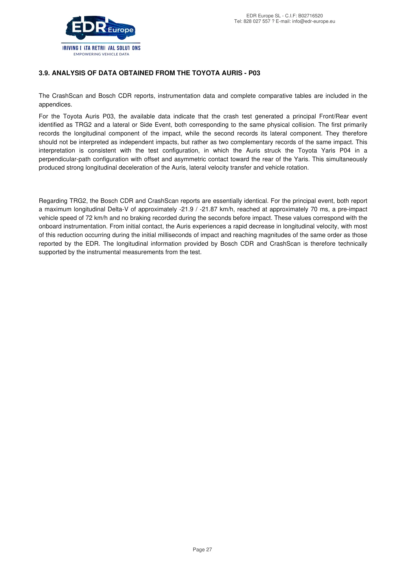
EDR Europe SL - C.I.F: B02716520 Tel: 828 027 557 ? E-mail: info@edr-europe.eu Page 26 3.8. COLLISION SEQUENCE The following images show the collision sequence at 30 millisecond intervals during the period from 0 to 210 ms, based upon the measurement system installed in the vehicles by DSD.
Read page 27 text
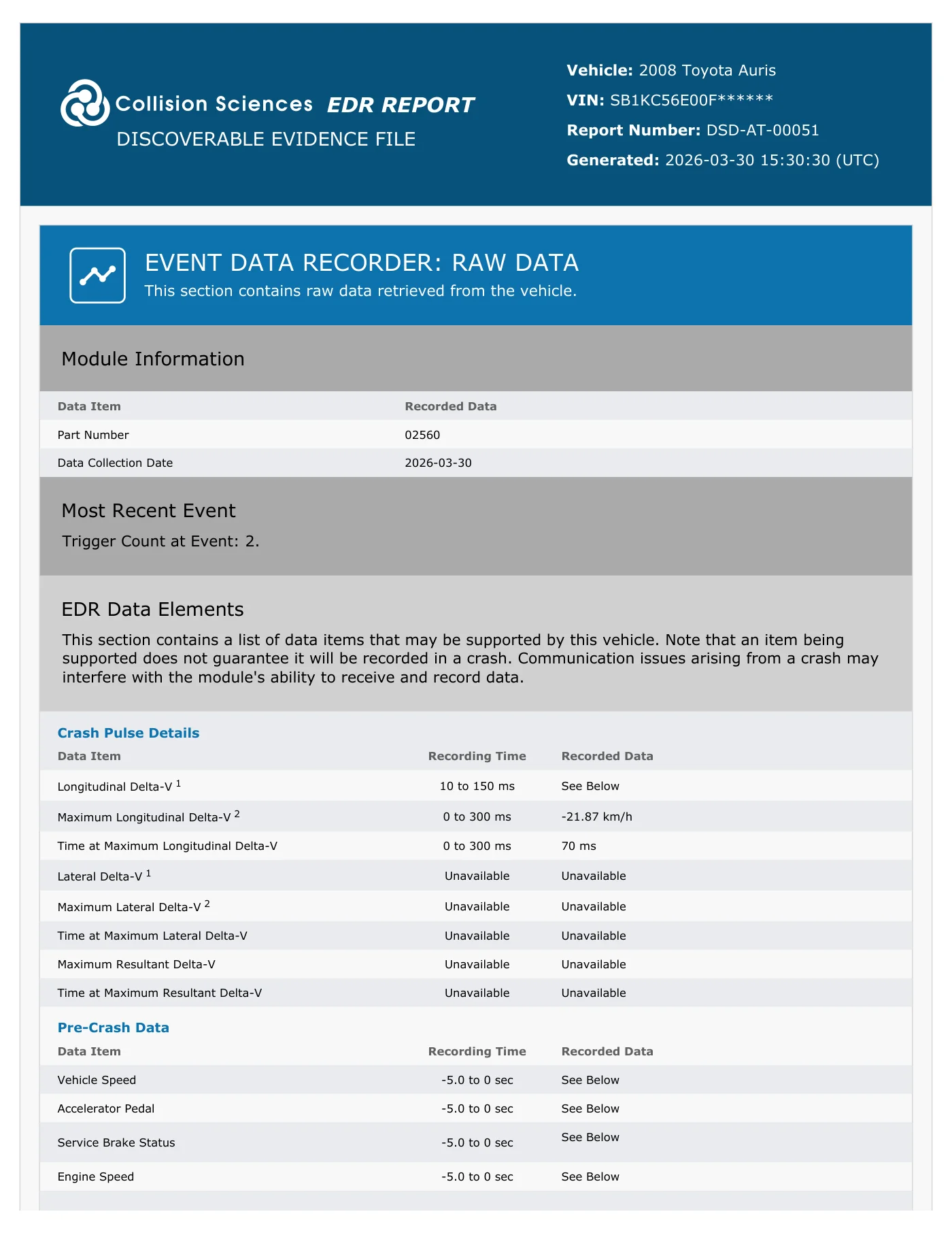
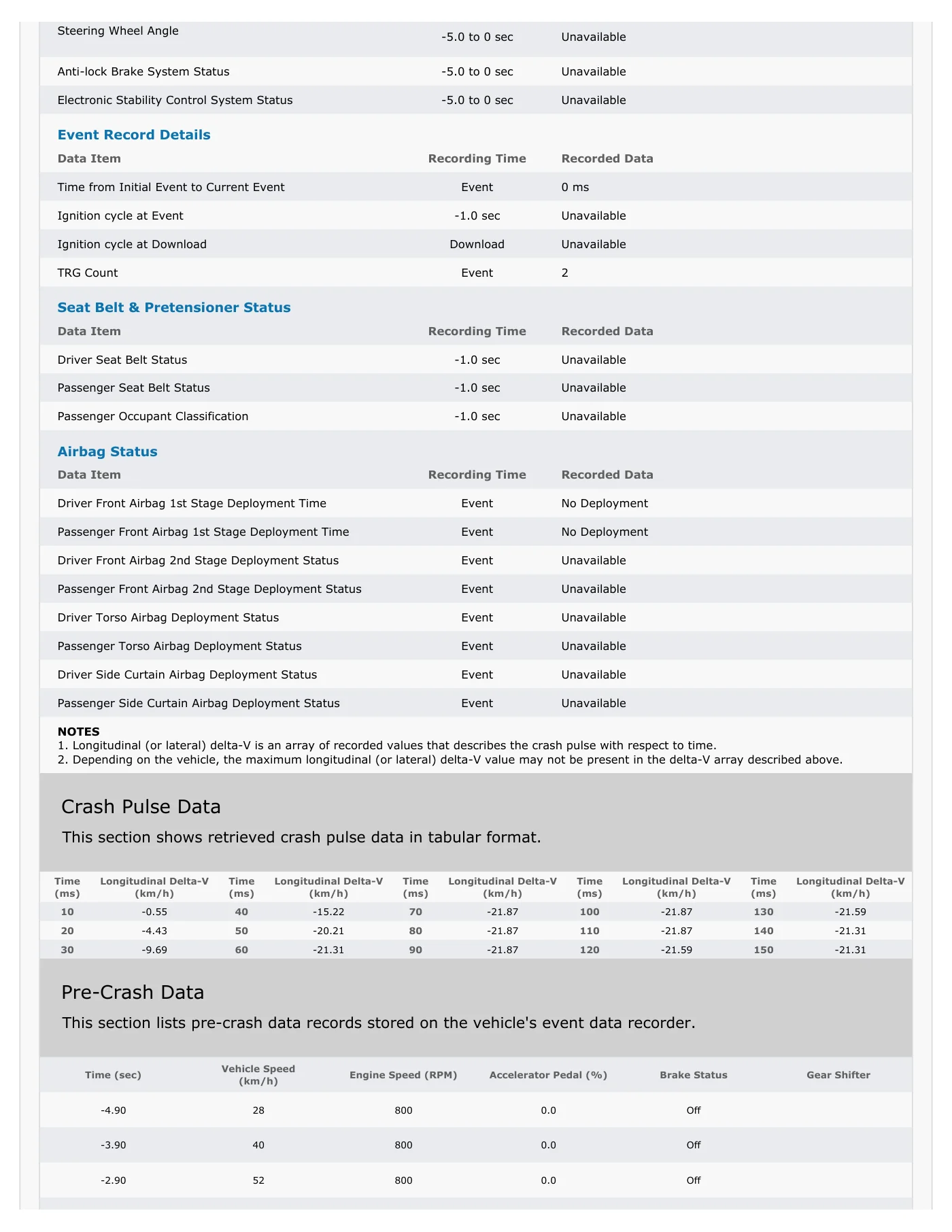
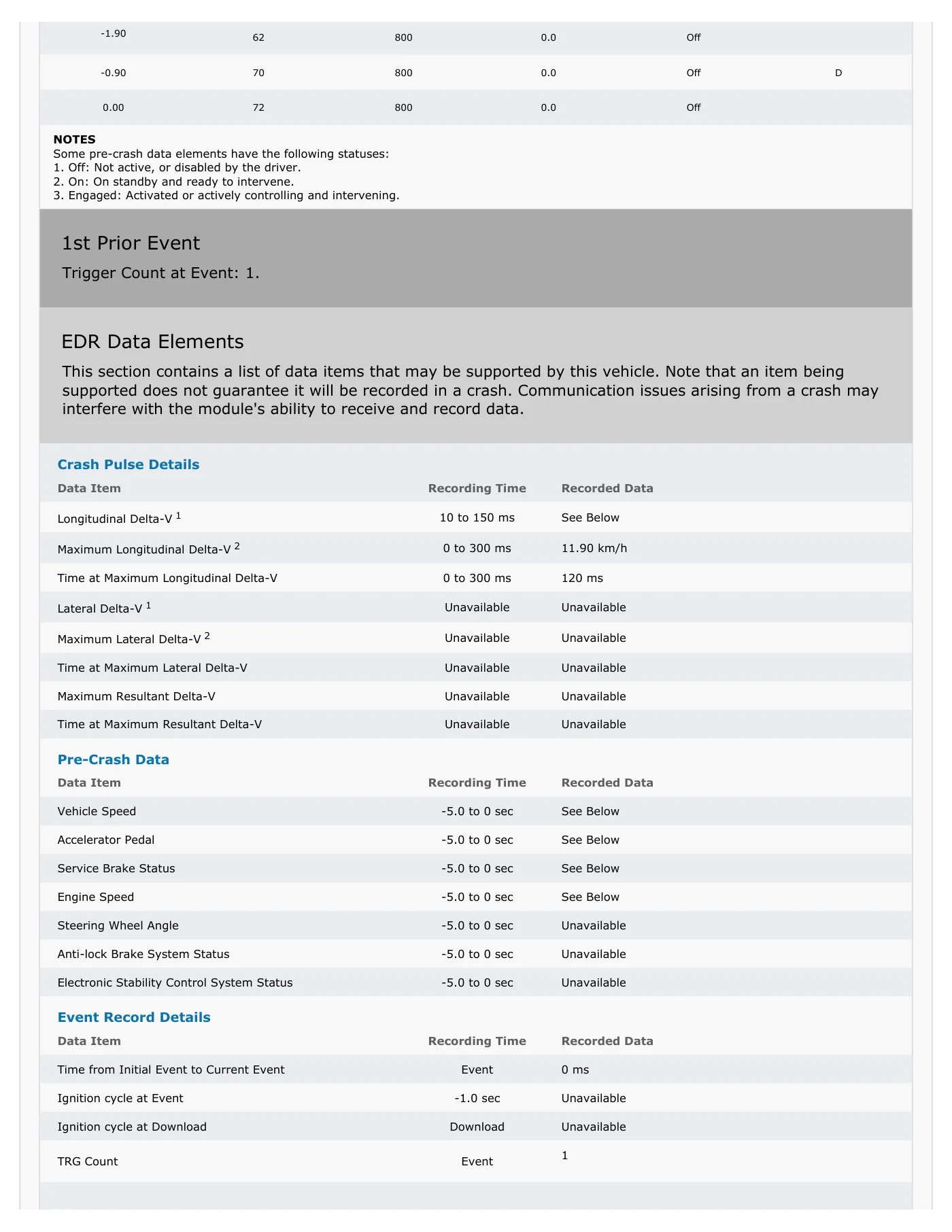
EDR Europe SL - C.I.F: B02716520 Tel: 828 027 557 ? E-mail: info@edr-europe.eu Page 27 3.9. ANALYSIS OF DATA OBTAINED FROM THE TOYOTA AURIS - P03 The CrashScan and Bosch CDR reports, instrumentation data and complete comparative tables are included in the appendices. For the Toyota Auris P03, the available data indicate that the crash test generated a principal Front/Rear event identified as TRG2 and a lateral or Side Event, both corresponding to the same physical collision. The first primarily records the longitudinal component of the impact, while the second records its lateral component. They therefore should not be interpreted as independent impacts, but rather as two complementary records of the same impact. This interpretation is consistent with the test configuration, in which the Auris struck the Toyota Yaris P04 in a perpendicular-path configuration with offset and asymmetric contact toward the rear of the Yaris. This simultaneously produced strong longitudinal deceleration of the Auris, lateral velocity transfer and vehicle rotation. Regarding TRG2, the Bosch CDR and CrashScan reports are essentially identical. For the principal event, both report a maximum longitudinal Delta-V of approximately -21.9 / -21.87 km/h, reached at approximately 70 ms, a pre-impact vehicle speed of 72 km/h and no braking recorded during the seconds before impact. These values correspond with the onboard instrumentation. From initial contact, the Auris experiences a rapid decrease in longitudinal velocity, with most of this reduction occurring during the initial milliseconds of impact and reaching magnitudes of the same order as those reported by the EDR. The longitudinal information provided by Bosch CDR and CrashScan is therefore technically supported by the instrumental measurements from the test.
Read page 28 text
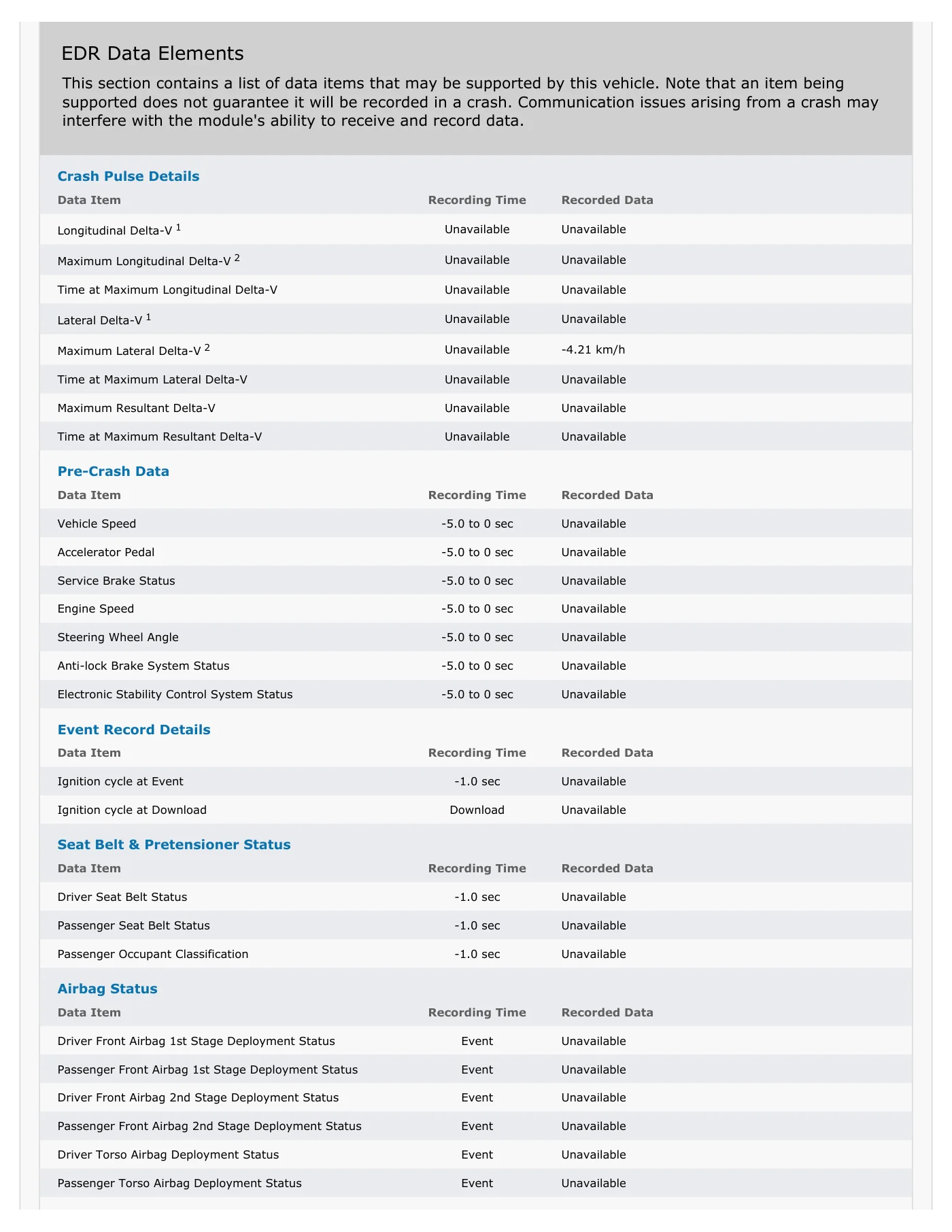
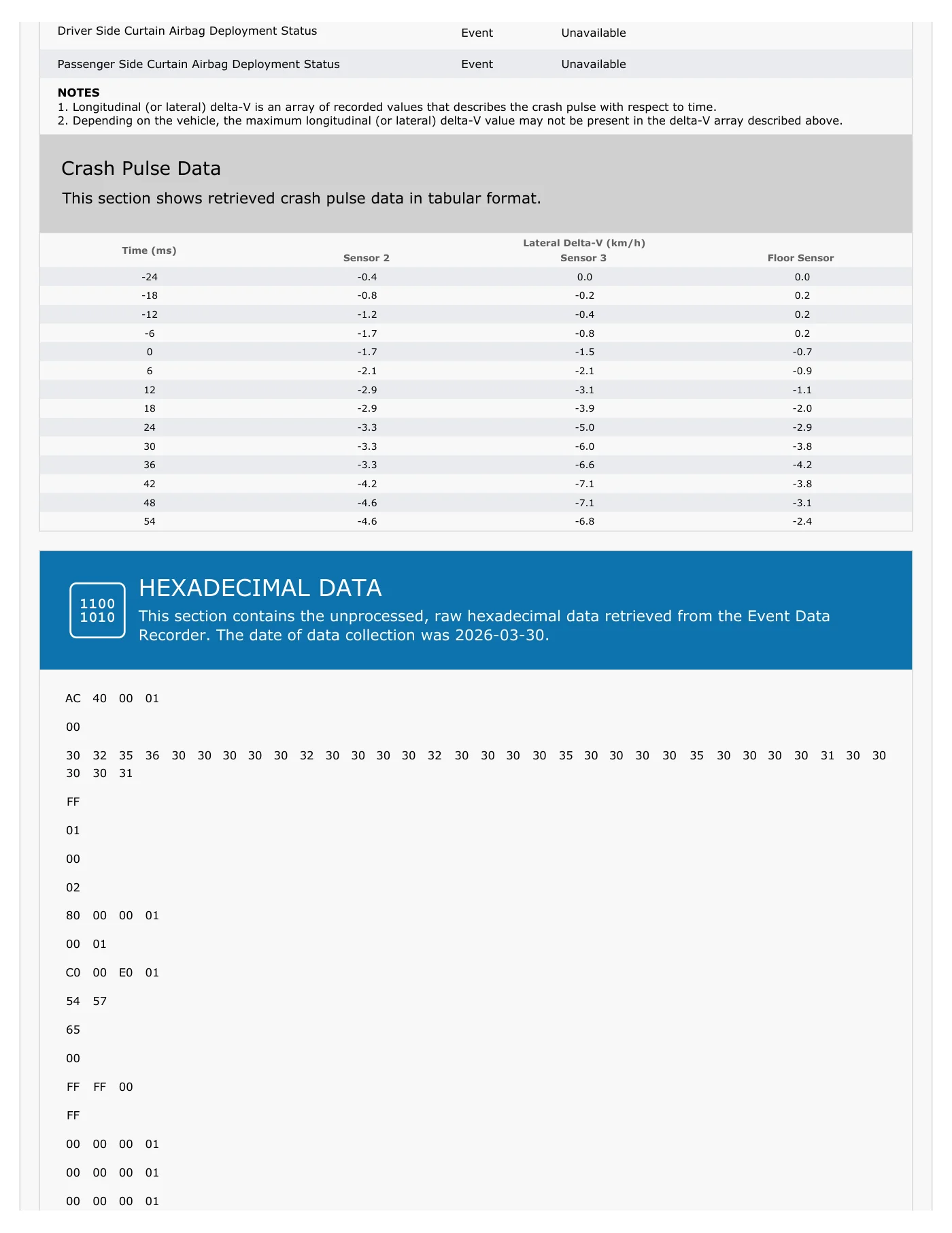
EDR Europe SL - C.I.F: B02716520 Tel: 828 027 557 ? E-mail: info@edr-europe.eu Page 28 The Side Event represents the lateral response generated during the same collision. CrashScan reports a maximum lateral value of -4.21 km/h. Bosch provides lateral values at 6 millisecond intervals and shows maximum values of approximately -4.2 km/h at the ECU sensor, -4.6 km/h at the B-pillar sensor and -7.1 km/h at the C-pillar sensor. Vehicle instrumentation likewise confirms the presence of both a lateral component and rotation of the Auris during the same initial impact interval, naturally associating the Side Event with TRG2. In other words, TRG2 describes the vehicle's forward velocity loss, while the Side Event describes the lateral deviation associated with the same contact. It must be recognized that the internal timing of the two records does not have to be exactly identical because Toyota lateral events have their own time reference, and the TRG Count applies only to Front/Rear events. Bosch expressly states in its Data Limitations that a lateral event uses its own temporal origin and that Side Events are not part of the Front/Rear TRG sequence. Nevertheless, from a physical and reconstruction standpoint, the instrumentation demonstrates that both responses occur within the same dynamic crash-test process, so their relationship is clear. It can consequently be concluded that in the Toyota Auris P03 the crash test generated the principal event TRG2 and the corresponding Side Event. The two events are mutually compatible and consistent with the observed test kinematics. The data supplied by CrashScan also demonstrate full agreement with the data obtained using Bosch CDR and with the vehicle instrumentation, supporting the technical correspondence of CrashScan data with Bosch CDR and the independent vehicle instrumentation in this specific case.
Read page 29 text
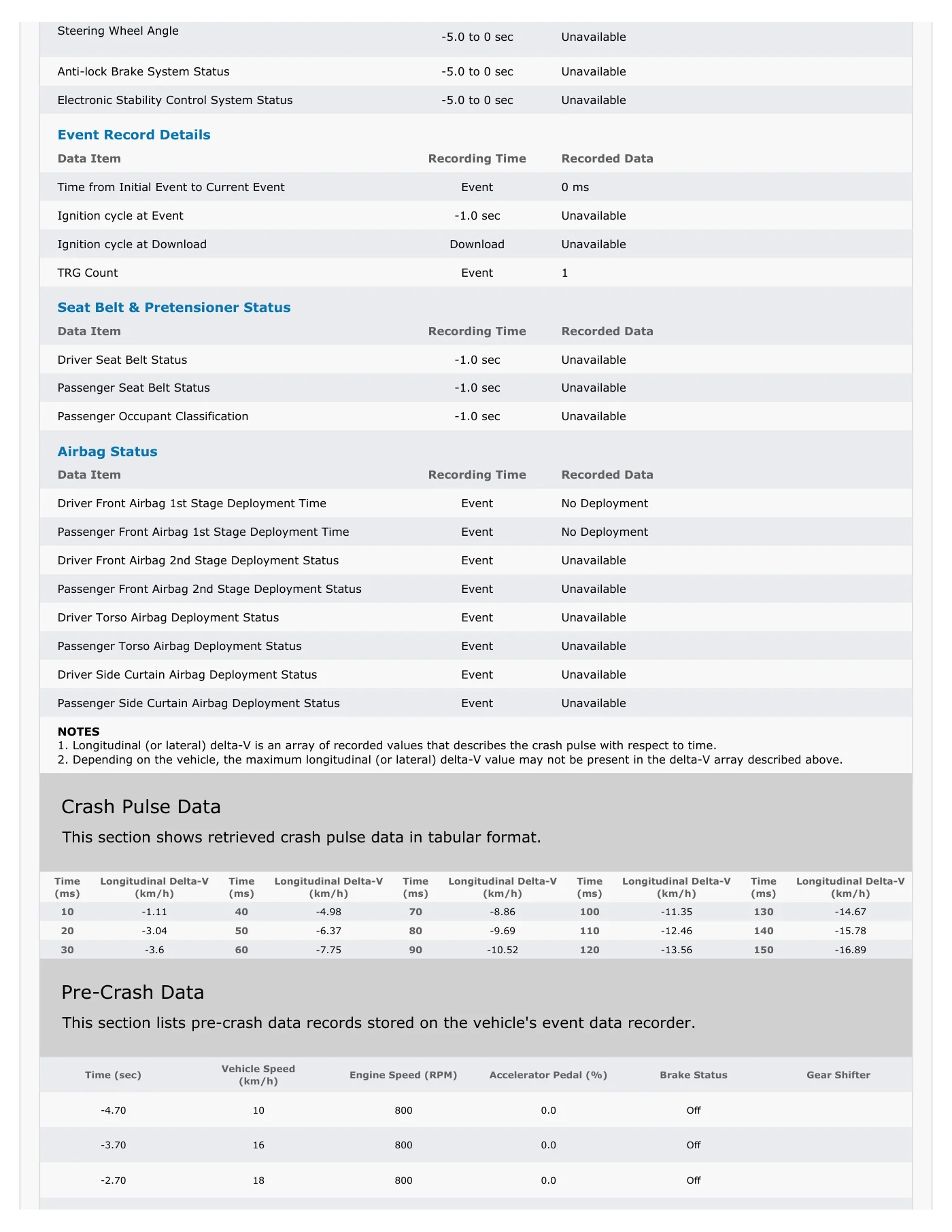
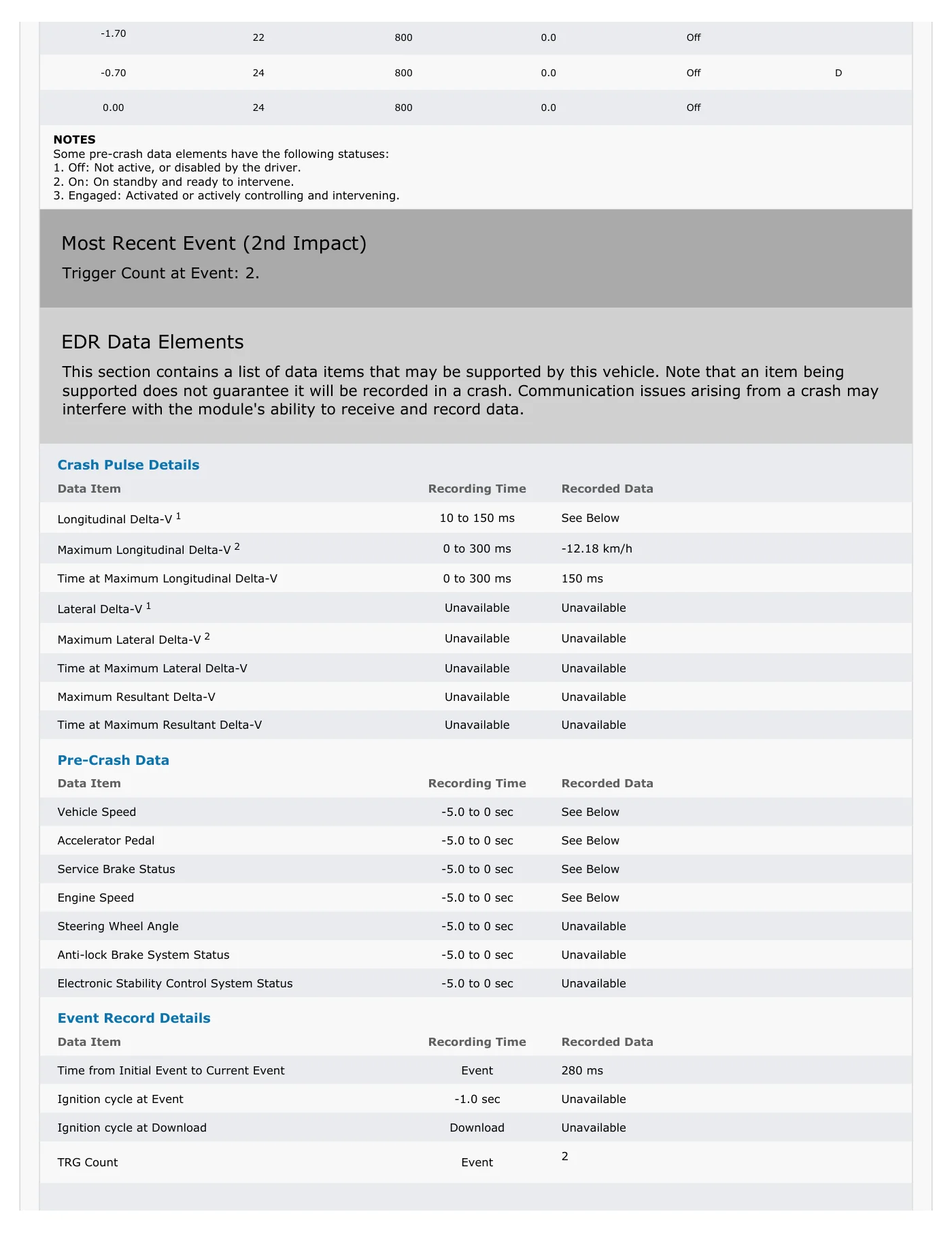
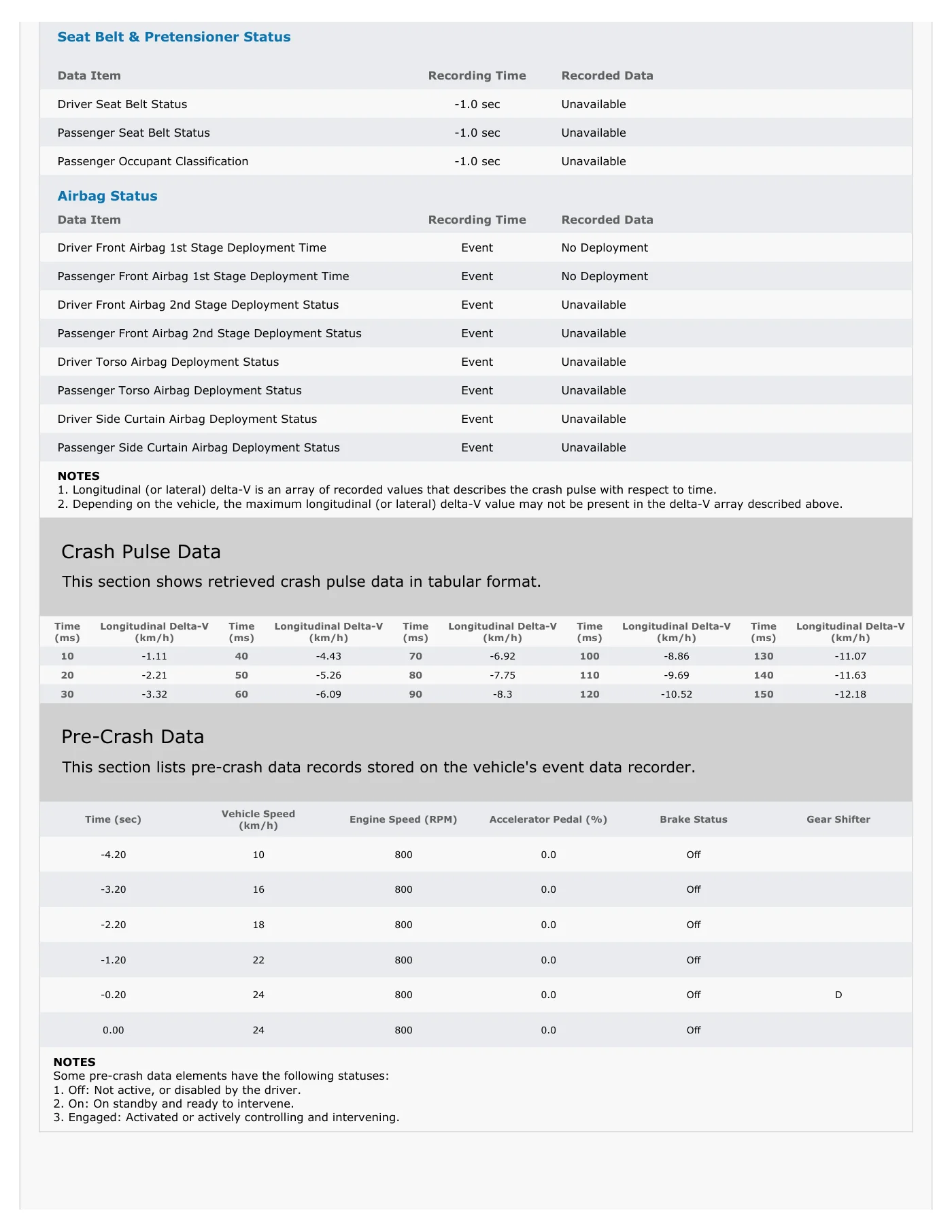
EDR Europe SL - C.I.F: B02716520 Tel: 828 027 557 ? E-mail: info@edr-europe.eu Page 29 3.10. ANALYSIS OF DATA OBTAINED FROM THE TOYOTA YARIS - P04 The CrashScan and Bosch CDR reports, instrumentation data and complete comparative tables are included in the appendices. Joint analysis of the Bosch CDR report, CrashScan report, test image sequence and Toyota Yaris P04 instrumentation indicates that TRG 1 and TRG 2 represent two successive phases of the same accident rather than two independent events. Both Bosch and CrashScan indicate that the retrieved module contains two Front/Rear events, identified as TRG Count 1 and TRG Count 2, separated by 280 ms, suggesting a single continuous collision sequence. Agreement between the two systems is nearly complete. In TRG 1, Bosch records a maximum longitudinal Delta-V of -16.9 km/h at 150 ms, while CrashScan records -16.89 km/h at 150 ms. In TRG 2, Bosch records -12.2 km/h at 150 ms and CrashScan records -12.18 km/h at 150 ms. The pre-crash data also agree: both reports show speeds of 10, 16, 18, 22 and 24 km/h, brake not applied, engine speed of 800 rpm and no deployment of the front airbags. The vehicle instrumentation provides physical consistency with these records. Immediately before impact, the Yaris was travelling at approximately 24 to 25 km/h, consistent with the 24 km/h recorded by Bosch and CrashScan. Following initial contact, the instrumentation shows a continuous vehicle response consisting of loss of longitudinal velocity, development of a transverse component and a progressive increase in rotation, without any appreciable dynamic interruption between the two phases. This behavior is fully compatible with generation of an initial principal trigger followed by a second trigger during the same collision episode. From an interpretive perspective, TRG 2 should be understood as a continuation of TRG 1. The 280 ms temporal separation is too short to reasonably support two independent accidents and corresponds to the observed test sequence, in which the Yaris receives the initial impact, rotates substantially and continues to undergo sufficient dynamic motion to generate a second longitudinal record.
Read page 30 text
EDR Europe SL - C.I.F: B02716520 Tel: 828 027 557 ? E-mail: info@edr-europe.eu Page 30 It is therefore technically reasonable to consider both triggers part of the same chain of structural interaction. It should also be noted that the EDR data available from this vehicle are essentially longitudinal. Bosch identifies the ECU as 02EDR with Front/Rear event retrieval, while CrashScan expressly identifies Lateral Delta-V and Maximum Resultant Delta-V as "Unavailable." The retrieved values therefore do not represent the total severity of the vehicle's motion, but only the longitudinal component of the change in velocity stored by the system. This is important for correct interpretation. In an offset and asymmetric impact such as the one analyzed, the vehicle's actual movement is not limited to its longitudinal axis, but also contains substantial lateral motion and rotation. Consequently, although the longitudinal Delta-V values recorded by Bosch and CrashScan are technically correct, their magnitude may be lower than the actual resultant severity of the movement of the vehicle's center of gravity. This is not an error in the EDR data, but an inherent limitation of the measurement channel available in this ECU and the fact that Bosch expressly warns that Longitudinal Delta-V represents the change in velocity following establishment of the trigger and does not necessarily include the complete velocity change occurring from the physical beginning of contact. In summary, data retrieved from the Toyota Yaris P04 demonstrate that CrashScan reproduces the information obtained using Bosch CDR with respect to number of events, temporal sequence, pre-crash speeds and longitudinal Delta-V values. The records are also consistent with the vehicle instrumentation and observable test dynamics. It can therefore be concluded that, in this case, the data provided by CrashScan demonstrate substantial technical correspondence with those obtained through Bosch CDR and are consistent with the available instrumentation and observable dynamics of the test.
Read page 31 text
EDR Europe SL - C.I.F: B02716520 Tel: 828 027 557 ? E-mail: info@edr-europe.eu Page 31 4. ASSESSMENT OF THE PARAMETERS ANALYZED Technical assessment of the retrieved data should focus particularly upon parameters that are most relevant to accident reconstruction and that can be compared among different information sources. Not all available data have the same technical value in this study. Certain parameters, such as pre-impact speed and Delta-V, are directly relevant to accident reconstruction and permit objective comparison among Bosch CDR, CrashScan and independent DSD instrumentation. Other parameters, such as accelerator status, engine speed or engine load, have less value in this particular test because the vehicles were not moving under their own power but were propelled using an external towing system. Accordingly, assessment of the correspondence among CrashScan, Bosch CDR and DSD should primarily consider parameters having direct value for accident reconstruction rather than applying equal technical weight to measurements that, because of the special test conditions, are not representative of normal driving. The following table summarizes the forensic value attributed to each group of data within this study:
Read page 32 text
EDR Europe SL - C.I.F: B02716520 Tel: 828 027 557 ? E-mail: info@edr-europe.eu Page 32 Data type Forensic value Possible comparison Observation Pre-impact speed High Bosch / CrashScan / DSD Important for comparing EDR-recorded speed against independent instrumentation. Longitudinal Delta-V Very high Bosch / CrashScan / DSD Central parameter of the study, particularly for Front/Rear events stored by Toyota 02EDR ECUs. Lateral Delta-V High / very high Bosch / CrashScan / DSD Particularly relevant in offset impacts or impacts with a lateral component when lateral recording is available. Event trigger timing High Bosch / CrashScan / video / DSD Allows EDR events to be associated with the physical sequence observed during the test. Brake / accelerator status Low in this test Bosch / CrashScan Reconstruction value is limited because of the external towing system used for the crash test. Engine speed / engine load Low in this test Bosch / CrashScan Does not represent normal driving because the vehicles were not moving under their own propulsion. Lateral sensors Medium- high Bosch / CrashScan / DSD Useful for identifying a lateral component, although results can be affected by sensor location and local structural response. Based upon these criteria, the comparative analysis should place greatest importance upon agreement in pre-impact speed, longitudinal Delta-V, available lateral records and temporal consistency of events. These parameters provide the strongest basis for assessing technical correspondence among CrashScan data, Bosch CDR data and independent DSD instrumentation. Conversely, accelerator position, engine speed and engine-load data should be interpreted cautiously because the test conditions did not reproduce normal self-propelled driving. Instead, the vehicles were moved using a controlled external propulsion system.
Read page 33 text
EDR Europe SL - C.I.F: B02716520 Tel: 828 027 557 ? E-mail: info@edr-europe.eu Page 33 5. FINAL CONSIDERATIONS The study produces the following final conclusions: 1. CrashScan has a technically defined architecture for remote acquisition of EDR data based upon communication among the vehicle, an OBD interface, a mobile application and remote processing infrastructure. According to information supplied by Collision Sciences, the system retains the raw data retrieved from the vehicle together with metadata and technical records associated with the retrieval. 2. From an information-security standpoint, CrashScan incorporates transmission using HTTPS/TLS 1.3, storage within AWS infrastructure using AES-256 encryption and logical separation of users by organization. These measures contribute to protecting information during transmission and storage and to restricting data access to the appropriate organization. However, no specific cryptographic mechanism such as a hash, checksum or digital signature has been reported as being applied directly to uploaded data. Accordingly, this should be considered in cases requiring independent cryptographic verification of data integrity. 3. In the analyzed test, data obtained through CrashScan demonstrate substantial technical correspondence with data retrieved using Bosch CDR. Numerical differences observed in directly comparable parameters are minimal and are compatible with differences in rounding, formatting or presentation between the reports. 4. The retrieved EDR events are consistent with the configuration of the crash test and the dynamics observed during the test. The recorded information makes it possible to identify the principal phases of the impact and associate them with the physical sequence documented using images and independent instrumentation.
Read page 34 text
EDR Europe SL - C.I.F: B02716520 Tel: 828 027 557 ? E-mail: info@edr-europe.eu Page 34 5. Comparison against the instrumentation installed by DSD confirms the general consistency of the retrieved EDR data, particularly with respect to pre-impact speed, changes in velocity during the collision pulse, temporal consistency of the events and the general dynamic response of the vehicles during the test. This comparison must be interpreted with the understanding that EDR modules use their own internal triggering, filtering, integration and storage criteria. Exact point-by-point agreement with external test instrumentation should therefore not necessarily be expected. 6. During this crash test, the vehicles were moved using an external towing system rather than under their own propulsion. Parameters such as accelerator position, engine speed and engine load therefore have less accident-reconstruction value than pre-impact speed, Delta-V, temporal consistency of events and compatibility with the observed physical sequence. 7. Consequently, the data obtained through CrashScan coincide with those obtained using Bosch CDR and are consistent with the independent instrumentation installed by DSD. EDR Europe SL Solutions Team Date: April 23, 2026

Read page 35 text
EDR Europe SL - C.I.F: B02716520 Tel: 828 027 557 ? E-mail: info@edr-europe.eu Page 35 APPENDICES

Read page 36 text
EDR Europe SL - C.I.F: B02716520 Tfno: 828 027 557 • E-mail: info@edr-europe.eu ANEXO 1: Informe de CrashScan
Read page 37 text
EVENT DATA RECORDER: RAW DATA This section contains raw data retrieved from the vehicle. Module Information Data Item Recorded Data Part Number 02560 Data Collection Date 2026-03-30 Most Recent Event Trigger Count at Event: 2. EDR Data Elements This section contains a list of data items that may be supported by this vehicle. Note that an item being supported does not guarantee it will be recorded in a crash. Communication issues arising from a crash may interfere with the module's ability to receive and record data. Crash Pulse Details Data Item Recording Time Recorded Data Longitudinal Delta-V 1 10 to 150 ms See Below Maximum Longitudinal Delta-V 2 0 to 300 ms -21.87 km/h Time at Maximum Longitudinal Delta-V 0 to 300 ms 70 ms Lateral Delta-V 1 Unavailable Unavailable Maximum Lateral Delta-V 2 Unavailable Unavailable Time at Maximum Lateral Delta-V Unavailable Unavailable Maximum Resultant Delta-V Unavailable Unavailable Time at Maximum Resultant Delta-V Unavailable Unavailable Pre-Crash Data Data Item Recording Time Recorded Data Vehicle Speed -5.0 to 0 sec See Below Accelerator Pedal -5.0 to 0 sec See Below Service Brake Status -5.0 to 0 sec See Below Engine Speed -5.0 to 0 sec See Below EDR REPORT DISCOVERABLE EVIDENCE FILE Vehicle: 2008 Toyota Auris VIN: SB1KC56E00F****** Report Number: DSD-AT-00051 Generated: 2026-03-30 15:30:30 (UTC)
Read page 38 text
Steering Wheel Angle -5.0 to 0 sec Unavailable Anti-lock Brake System Status -5.0 to 0 sec Unavailable Electronic Stability Control System Status -5.0 to 0 sec Unavailable Event Record Details Data Item Recording Time Recorded Data Time from Initial Event to Current Event Event 0 ms Ignition cycle at Event -1.0 sec Unavailable Ignition cycle at Download Download Unavailable TRG Count Event 2 Seat Belt & Pretensioner Status Data Item Recording Time Recorded Data Driver Seat Belt Status -1.0 sec Unavailable Passenger Seat Belt Status -1.0 sec Unavailable Passenger Occupant Classification -1.0 sec Unavailable Airbag Status Data Item Recording Time Recorded Data Driver Front Airbag 1st Stage Deployment Time Event No Deployment Passenger Front Airbag 1st Stage Deployment Time Event No Deployment Driver Front Airbag 2nd Stage Deployment Status Event Unavailable Passenger Front Airbag 2nd Stage Deployment Status Event Unavailable Driver Torso Airbag Deployment Status Event Unavailable Passenger Torso Airbag Deployment Status Event Unavailable Driver Side Curtain Airbag Deployment Status Event Unavailable Passenger Side Curtain Airbag Deployment Status Event Unavailable NOTES 1. Longitudinal (or lateral) delta-V is an array of recorded values that describes the crash pulse with respect to time. 2. Depending on the vehicle, the maximum longitudinal (or lateral) delta-V value may not be present in the delta-V array described above. Crash Pulse Data This section shows retrieved crash pulse data in tabular format. Time (ms) Longitudinal Delta-V (km/h) Time (ms) Longitudinal Delta-V (km/h) Time (ms) Longitudinal Delta-V (km/h) Time (ms) Longitudinal Delta-V (km/h) Time (ms) Longitudinal Delta-V (km/h) 10 -0.55 40 -15.22 70 -21.87 100 -21.87 130 -21.59 20 -4.43 50 -20.21 80 -21.87 110 -21.87 140 -21.31 30 -9.69 60 -21.31 90 -21.87 120 -21.59 150 -21.31 Pre-Crash Data This section lists pre-crash data records stored on the vehicle's event data recorder. Time (sec) Vehicle Speed (km/h) Engine Speed (RPM) Accelerator Pedal (%) Brake Status Gear Shifter -4.90 28 800 0.0 Off -3.90 40 800 0.0 Off -2.90 52 800 0.0 Off
Read page 39 text
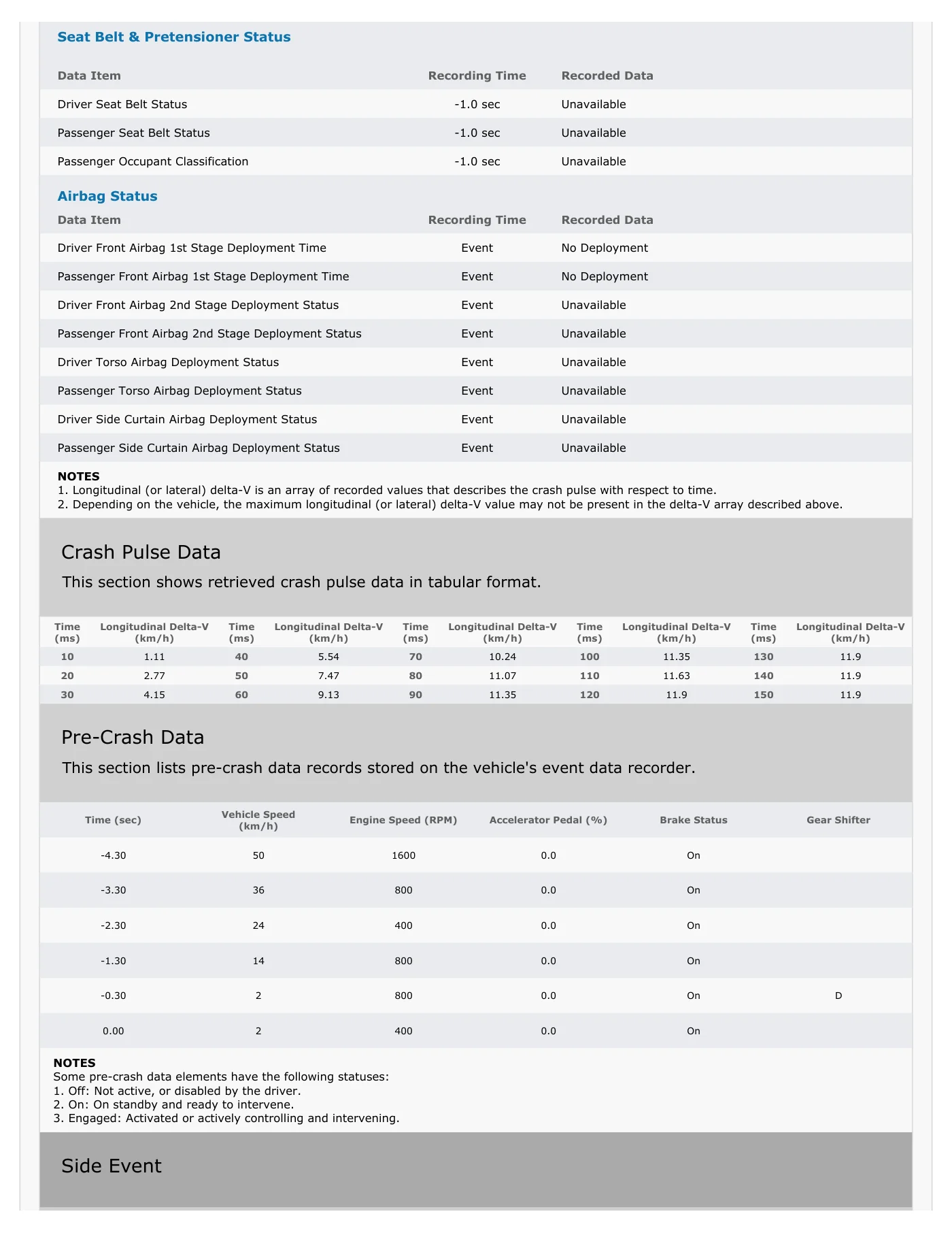
-1.90 62 800 0.0 Off -0.90 70 800 0.0 Off D 0.00 72 800 0.0 Off NOTES Some pre-crash data elements have the following statuses: 1. Off: Not active, or disabled by the driver. 2. On: On standby and ready to intervene. 3. Engaged: Activated or actively controlling and intervening. 1st Prior Event Trigger Count at Event: 1. EDR Data Elements This section contains a list of data items that may be supported by this vehicle. Note that an item being supported does not guarantee it will be recorded in a crash. Communication issues arising from a crash may interfere with the module's ability to receive and record data. Crash Pulse Details Data Item Recording Time Recorded Data Longitudinal Delta-V 1 10 to 150 ms See Below Maximum Longitudinal Delta-V 2 0 to 300 ms 11.90 km/h Time at Maximum Longitudinal Delta-V 0 to 300 ms 120 ms Lateral Delta-V 1 Unavailable Unavailable Maximum Lateral Delta-V 2 Unavailable Unavailable Time at Maximum Lateral Delta-V Unavailable Unavailable Maximum Resultant Delta-V Unavailable Unavailable Time at Maximum Resultant Delta-V Unavailable Unavailable Pre-Crash Data Data Item Recording Time Recorded Data Vehicle Speed -5.0 to 0 sec See Below Accelerator Pedal -5.0 to 0 sec See Below Service Brake Status -5.0 to 0 sec See Below Engine Speed -5.0 to 0 sec See Below Steering Wheel Angle -5.0 to 0 sec Unavailable Anti-lock Brake System Status -5.0 to 0 sec Unavailable Electronic Stability Control System Status -5.0 to 0 sec Unavailable Event Record Details Data Item Recording Time Recorded Data Time from Initial Event to Current Event Event 0 ms Ignition cycle at Event -1.0 sec Unavailable Ignition cycle at Download Download Unavailable TRG Count Event 1
Read page 40 text
Seat Belt & Pretensioner Status Data Item Recording Time Recorded Data Driver Seat Belt Status -1.0 sec Unavailable Passenger Seat Belt Status -1.0 sec Unavailable Passenger Occupant Classification -1.0 sec Unavailable Airbag Status Data Item Recording Time Recorded Data Driver Front Airbag 1st Stage Deployment Time Event No Deployment Passenger Front Airbag 1st Stage Deployment Time Event No Deployment Driver Front Airbag 2nd Stage Deployment Status Event Unavailable Passenger Front Airbag 2nd Stage Deployment Status Event Unavailable Driver Torso Airbag Deployment Status Event Unavailable Passenger Torso Airbag Deployment Status Event Unavailable Driver Side Curtain Airbag Deployment Status Event Unavailable Passenger Side Curtain Airbag Deployment Status Event Unavailable NOTES 1. Longitudinal (or lateral) delta-V is an array of recorded values that describes the crash pulse with respect to time. 2. Depending on the vehicle, the maximum longitudinal (or lateral) delta-V value may not be present in the delta-V array described above. Crash Pulse Data This section shows retrieved crash pulse data in tabular format. Time (ms) Longitudinal Delta-V (km/h) Time (ms) Longitudinal Delta-V (km/h) Time (ms) Longitudinal Delta-V (km/h) Time (ms) Longitudinal Delta-V (km/h) Time (ms) Longitudinal Delta-V (km/h) 10 1.11 40 5.54 70 10.24 100 11.35 130 11.9 20 2.77 50 7.47 80 11.07 110 11.63 140 11.9 30 4.15 60 9.13 90 11.35 120 11.9 150 11.9 Pre-Crash Data This section lists pre-crash data records stored on the vehicle's event data recorder. Time (sec) Vehicle Speed (km/h) Engine Speed (RPM) Accelerator Pedal (%) Brake Status Gear Shifter -4.30 50 1600 0.0 On -3.30 36 800 0.0 On -2.30 24 400 0.0 On -1.30 14 800 0.0 On -0.30 2 800 0.0 On D 0.00 2 400 0.0 On NOTES Some pre-crash data elements have the following statuses: 1. Off: Not active, or disabled by the driver. 2. On: On standby and ready to intervene. 3. Engaged: Activated or actively controlling and intervening. Side Event
Read page 41 text
EDR Data Elements This section contains a list of data items that may be supported by this vehicle. Note that an item being supported does not guarantee it will be recorded in a crash. Communication issues arising from a crash may interfere with the module's ability to receive and record data. Crash Pulse Details Data Item Recording Time Recorded Data Longitudinal Delta-V 1 Unavailable Unavailable Maximum Longitudinal Delta-V 2 Unavailable Unavailable Time at Maximum Longitudinal Delta-V Unavailable Unavailable Lateral Delta-V 1 Unavailable Unavailable Maximum Lateral Delta-V 2 Unavailable -4.21 km/h Time at Maximum Lateral Delta-V Unavailable Unavailable Maximum Resultant Delta-V Unavailable Unavailable Time at Maximum Resultant Delta-V Unavailable Unavailable Pre-Crash Data Data Item Recording Time Recorded Data Vehicle Speed -5.0 to 0 sec Unavailable Accelerator Pedal -5.0 to 0 sec Unavailable Service Brake Status -5.0 to 0 sec Unavailable Engine Speed -5.0 to 0 sec Unavailable Steering Wheel Angle -5.0 to 0 sec Unavailable Anti-lock Brake System Status -5.0 to 0 sec Unavailable Electronic Stability Control System Status -5.0 to 0 sec Unavailable Event Record Details Data Item Recording Time Recorded Data Ignition cycle at Event -1.0 sec Unavailable Ignition cycle at Download Download Unavailable Seat Belt & Pretensioner Status Data Item Recording Time Recorded Data Driver Seat Belt Status -1.0 sec Unavailable Passenger Seat Belt Status -1.0 sec Unavailable Passenger Occupant Classification -1.0 sec Unavailable Airbag Status Data Item Recording Time Recorded Data Driver Front Airbag 1st Stage Deployment Status Event Unavailable Passenger Front Airbag 1st Stage Deployment Status Event Unavailable Driver Front Airbag 2nd Stage Deployment Status Event Unavailable Passenger Front Airbag 2nd Stage Deployment Status Event Unavailable Driver Torso Airbag Deployment Status Event Unavailable Passenger Torso Airbag Deployment Status Event Unavailable
Read page 42 text
Driver Side Curtain Airbag Deployment Status Event Unavailable Passenger Side Curtain Airbag Deployment Status Event Unavailable NOTES 1. Longitudinal (or lateral) delta-V is an array of recorded values that describes the crash pulse with respect to time. 2. Depending on the vehicle, the maximum longitudinal (or lateral) delta-V value may not be present in the delta-V array described above. Crash Pulse Data This section shows retrieved crash pulse data in tabular format. Time (ms) Lateral Delta-V (km/h) Sensor 2 Sensor 3 Floor Sensor -24 -0.4 0.0 0.0 -18 -0.8 -0.2 0.2 -12 -1.2 -0.4 0.2 -6 -1.7 -0.8 0.2 0 -1.7 -1.5 -0.7 6 -2.1 -2.1 -0.9 12 -2.9 -3.1 -1.1 18 -2.9 -3.9 -2.0 24 -3.3 -5.0 -2.9 30 -3.3 -6.0 -3.8 36 -3.3 -6.6 -4.2 42 -4.2 -7.1 -3.8 48 -4.6 -7.1 -3.1 54 -4.6 -6.8 -2.4 HEXADECIMAL DATA This section contains the unprocessed, raw hexadecimal data retrieved from the Event Data Recorder. The date of data collection was 2026-03-30. AC 40 00 01 00 30 32 35 36 30 30 30 30 30 32 30 30 30 30 32 30 30 30 30 35 30 30 30 30 35 30 30 30 30 31 30 30 30 30 31 FF 01 00 02 80 00 00 01 00 01 C0 00 E0 01 54 57 65 00 FF FF 00 FF 00 00 00 01 00 00 00 01 00 00 00 01
Read page 43 text
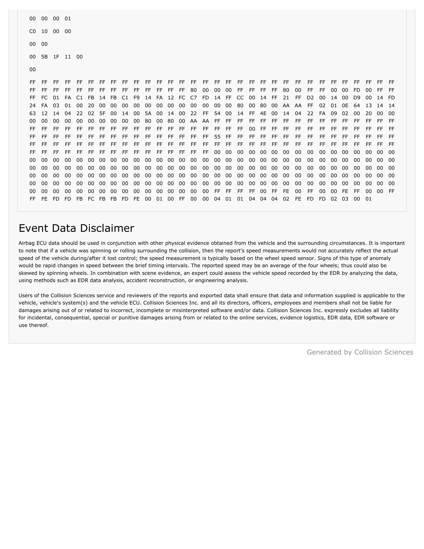
00 00 00 01 C0 10 00 00 00 00 00 5B 1F 11 00 00 FF FF FF FF FF FF FF FF FF FF FF FF FF FF FF FF FF FF FF FF FF FF FF FF FF FF FF FF FF FF FF FF FF FF FF FF FF FF FF FF FF FF FF FF FF FF 80 00 00 00 FF FF FF FF 80 00 FF FF 00 00 FD 00 FF FF FF FC 01 FA C1 FB 14 FB C1 F9 14 FA 12 FC C7 FD 14 FF CC 00 14 FF 21 FF D2 00 14 00 D9 00 14 FD 24 FA 03 01 00 20 00 00 00 00 00 00 00 00 00 00 00 00 80 00 80 00 AA AA FF 02 01 0E 64 13 14 14 63 12 14 04 22 02 5F 00 14 00 5A 00 14 00 22 FF 54 00 14 FF 4E 00 14 04 22 FA 09 02 00 20 00 00 00 00 00 00 00 00 00 00 00 00 80 00 80 00 AA AA FF FF FF FF FF FF FF FF FF FF FF FF FF FF FF FF FF FF FF FF FF FF FF FF FF FF FF FF FF FF FF FF FF FF FF 00 FF FF FF FF FF FF FF FF FF FF FF FF FF FF FF FF FF FF FF FF FF FF FF FF FF FF FF FF 55 FF FF FF FF FF FF FF FF FF FF FF FF FF FF FF FF FF FF FF FF FF FF FF FF FF FF FF FF FF FF FF FF FF FF FF FF FF FF FF FF FF FF FF FF FF FF FF FF FF FF FF FF FF FF FF FF FF FF FF FF FF FF FF 00 00 00 00 00 00 00 00 00 00 00 00 00 00 00 00 00 00 00 00 00 00 00 00 00 00 00 00 00 00 00 00 00 00 00 00 00 00 00 00 00 00 00 00 00 00 00 00 00 00 00 00 00 00 00 00 00 00 00 00 00 00 00 00 00 00 00 00 00 00 00 00 00 00 00 00 00 00 00 00 00 00 00 00 00 00 00 00 00 00 00 00 00 00 00 00 00 00 00 00 00 00 00 00 00 00 00 00 00 00 00 00 00 00 00 00 00 00 00 00 00 00 00 00 00 00 00 00 00 00 00 00 00 00 00 00 00 00 00 00 00 00 00 00 00 00 00 00 00 00 00 00 00 00 00 00 00 00 00 00 FF FF FF FF 00 FF FE 00 FF 00 00 FE FF 00 00 FF FF FE FD FD FB FC FB FB FD FE 00 01 00 FF 00 00 04 01 01 04 04 04 02 FE FD FD 02 03 00 01 Event Data Disclaimer Airbag ECU data should be used in conjunction with other physical evidence obtained from the vehicle and the surrounding circumstances. It is important to note that if a vehicle was spinning or rolling surrounding the collision, then the report's speed measurements would not accurately reflect the actual speed of the vehicle during/after it lost control; the speed measurement is typically based on the wheel speed sensor. Signs of this type of anomaly would be rapid changes in speed between the brief timing intervals. The reported speed may be an average of the four wheels; thus could also be skewed by spinning wheels. In combination with scene evidence, an expert could assess the vehicle speed recorded by the EDR by analyzing the data, using methods such as EDR data analysis, accident reconstruction, or engineering analysis. Users of the Collision Sciences service and reviewers of the reports and exported data shall ensure that data and information supplied is applicable to the vehicle, vehicle's system(s) and the vehicle ECU. Collision Sciences Inc. and all its directors, officers, employees and members shall not be liable for damages arising out of or related to incorrect, incomplete or misinterpreted software and/or data. Collision Sciences Inc. expressly excludes all liability for incidental, consequential, special or punitive damages arising from or related to the online services, evidence logistics, EDR data, EDR software or use thereof. Generated by Collision Sciences
Read page 44 text
EVENT DATA RECORDER: RAW DATA This section contains raw data retrieved from the vehicle. Module Information Data Item Recorded Data Part Number 0D430 Data Collection Date 2026-03-30 Most Recent Event (1st Impact) Trigger Count at Event: 1. EDR Data Elements This section contains a list of data items that may be supported by this vehicle. Note that an item being supported does not guarantee it will be recorded in a crash. Communication issues arising from a crash may interfere with the module's ability to receive and record data. Crash Pulse Details Data Item Recording Time Recorded Data Longitudinal Delta-V 1 10 to 150 ms See Below Maximum Longitudinal Delta-V 2 0 to 300 ms -16.89 km/h Time at Maximum Longitudinal Delta-V 0 to 300 ms 150 ms Lateral Delta-V 1 Unavailable Unavailable Maximum Lateral Delta-V 2 Unavailable Unavailable Time at Maximum Lateral Delta-V Unavailable Unavailable Maximum Resultant Delta-V Unavailable Unavailable Time at Maximum Resultant Delta-V Unavailable Unavailable Pre-Crash Data Data Item Recording Time Recorded Data Vehicle Speed -5.0 to 0 sec See Below Accelerator Pedal -5.0 to 0 sec See Below Service Brake Status -5.0 to 0 sec See Below Engine Speed -5.0 to 0 sec See Below EDR REPORT DISCOVERABLE EVIDENCE FILE Vehicle: 2011 Toyota Yaris VIN: VNKKG92360A****** Report Number: DSD-AT-00056 Generated: 2026-03-30 16:00:38 (UTC)
Read page 45 text
Steering Wheel Angle -5.0 to 0 sec Unavailable Anti-lock Brake System Status -5.0 to 0 sec Unavailable Electronic Stability Control System Status -5.0 to 0 sec Unavailable Event Record Details Data Item Recording Time Recorded Data Time from Initial Event to Current Event Event 0 ms Ignition cycle at Event -1.0 sec Unavailable Ignition cycle at Download Download Unavailable TRG Count Event 1 Seat Belt & Pretensioner Status Data Item Recording Time Recorded Data Driver Seat Belt Status -1.0 sec Unavailable Passenger Seat Belt Status -1.0 sec Unavailable Passenger Occupant Classification -1.0 sec Unavailable Airbag Status Data Item Recording Time Recorded Data Driver Front Airbag 1st Stage Deployment Time Event No Deployment Passenger Front Airbag 1st Stage Deployment Time Event No Deployment Driver Front Airbag 2nd Stage Deployment Status Event Unavailable Passenger Front Airbag 2nd Stage Deployment Status Event Unavailable Driver Torso Airbag Deployment Status Event Unavailable Passenger Torso Airbag Deployment Status Event Unavailable Driver Side Curtain Airbag Deployment Status Event Unavailable Passenger Side Curtain Airbag Deployment Status Event Unavailable NOTES 1. Longitudinal (or lateral) delta-V is an array of recorded values that describes the crash pulse with respect to time. 2. Depending on the vehicle, the maximum longitudinal (or lateral) delta-V value may not be present in the delta-V array described above. Crash Pulse Data This section shows retrieved crash pulse data in tabular format. Time (ms) Longitudinal Delta-V (km/h) Time (ms) Longitudinal Delta-V (km/h) Time (ms) Longitudinal Delta-V (km/h) Time (ms) Longitudinal Delta-V (km/h) Time (ms) Longitudinal Delta-V (km/h) 10 -1.11 40 -4.98 70 -8.86 100 -11.35 130 -14.67 20 -3.04 50 -6.37 80 -9.69 110 -12.46 140 -15.78 30 -3.6 60 -7.75 90 -10.52 120 -13.56 150 -16.89 Pre-Crash Data This section lists pre-crash data records stored on the vehicle's event data recorder. Time (sec) Vehicle Speed (km/h) Engine Speed (RPM) Accelerator Pedal (%) Brake Status Gear Shifter -4.70 10 800 0.0 Off -3.70 16 800 0.0 Off -2.70 18 800 0.0 Off
Read page 46 text
-1.70 22 800 0.0 Off -0.70 24 800 0.0 Off D 0.00 24 800 0.0 Off NOTES Some pre-crash data elements have the following statuses: 1. Off: Not active, or disabled by the driver. 2. On: On standby and ready to intervene. 3. Engaged: Activated or actively controlling and intervening. Most Recent Event (2nd Impact) Trigger Count at Event: 2. EDR Data Elements This section contains a list of data items that may be supported by this vehicle. Note that an item being supported does not guarantee it will be recorded in a crash. Communication issues arising from a crash may interfere with the module's ability to receive and record data. Crash Pulse Details Data Item Recording Time Recorded Data Longitudinal Delta-V 1 10 to 150 ms See Below Maximum Longitudinal Delta-V 2 0 to 300 ms -12.18 km/h Time at Maximum Longitudinal Delta-V 0 to 300 ms 150 ms Lateral Delta-V 1 Unavailable Unavailable Maximum Lateral Delta-V 2 Unavailable Unavailable Time at Maximum Lateral Delta-V Unavailable Unavailable Maximum Resultant Delta-V Unavailable Unavailable Time at Maximum Resultant Delta-V Unavailable Unavailable Pre-Crash Data Data Item Recording Time Recorded Data Vehicle Speed -5.0 to 0 sec See Below Accelerator Pedal -5.0 to 0 sec See Below Service Brake Status -5.0 to 0 sec See Below Engine Speed -5.0 to 0 sec See Below Steering Wheel Angle -5.0 to 0 sec Unavailable Anti-lock Brake System Status -5.0 to 0 sec Unavailable Electronic Stability Control System Status -5.0 to 0 sec Unavailable Event Record Details Data Item Recording Time Recorded Data Time from Initial Event to Current Event Event 280 ms Ignition cycle at Event -1.0 sec Unavailable Ignition cycle at Download Download Unavailable TRG Count Event 2
Read page 47 text
Seat Belt & Pretensioner Status Data Item Recording Time Recorded Data Driver Seat Belt Status -1.0 sec Unavailable Passenger Seat Belt Status -1.0 sec Unavailable Passenger Occupant Classification -1.0 sec Unavailable Airbag Status Data Item Recording Time Recorded Data Driver Front Airbag 1st Stage Deployment Time Event No Deployment Passenger Front Airbag 1st Stage Deployment Time Event No Deployment Driver Front Airbag 2nd Stage Deployment Status Event Unavailable Passenger Front Airbag 2nd Stage Deployment Status Event Unavailable Driver Torso Airbag Deployment Status Event Unavailable Passenger Torso Airbag Deployment Status Event Unavailable Driver Side Curtain Airbag Deployment Status Event Unavailable Passenger Side Curtain Airbag Deployment Status Event Unavailable NOTES 1. Longitudinal (or lateral) delta-V is an array of recorded values that describes the crash pulse with respect to time. 2. Depending on the vehicle, the maximum longitudinal (or lateral) delta-V value may not be present in the delta-V array described above. Crash Pulse Data This section shows retrieved crash pulse data in tabular format. Time (ms) Longitudinal Delta-V (km/h) Time (ms) Longitudinal Delta-V (km/h) Time (ms) Longitudinal Delta-V (km/h) Time (ms) Longitudinal Delta-V (km/h) Time (ms) Longitudinal Delta-V (km/h) 10 -1.11 40 -4.43 70 -6.92 100 -8.86 130 -11.07 20 -2.21 50 -5.26 80 -7.75 110 -9.69 140 -11.63 30 -3.32 60 -6.09 90 -8.3 120 -10.52 150 -12.18 Pre-Crash Data This section lists pre-crash data records stored on the vehicle's event data recorder. Time (sec) Vehicle Speed (km/h) Engine Speed (RPM) Accelerator Pedal (%) Brake Status Gear Shifter -4.20 10 800 0.0 Off -3.20 16 800 0.0 Off -2.20 18 800 0.0 Off -1.20 22 800 0.0 Off -0.20 24 800 0.0 Off D 0.00 24 800 0.0 Off NOTES Some pre-crash data elements have the following statuses: 1. Off: Not active, or disabled by the driver. 2. On: On standby and ready to intervene. 3. Engaged: Activated or actively controlling and intervening.
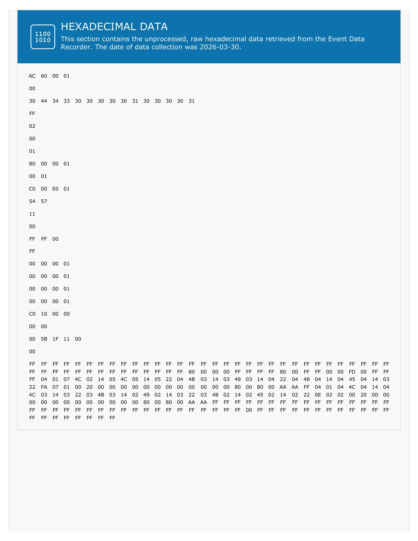
Read page 48 text
HEXADECIMAL DATA This section contains the unprocessed, raw hexadecimal data retrieved from the Event Data Recorder. The date of data collection was 2026-03-30. AC 60 00 01 00 30 44 34 33 30 30 30 30 30 31 30 30 30 30 31 FF 02 00 01 80 00 00 01 00 01 C0 00 E0 01 54 57 11 00 FF FF 00 FF 00 00 00 01 00 00 00 01 00 00 00 01 00 00 00 01 C0 10 00 00 00 00 00 5B 1F 11 00 00 FF FF FF FF FF FF FF FF FF FF FF FF FF FF FF FF FF FF FF FF FF FF FF FF FF FF FF FF FF FF FF FF FF FF FF FF FF FF FF FF FF FF FF FF FF FF 80 00 00 00 FF FF FF FF 80 00 FF FF 00 00 FD 00 FF FF FF 04 01 07 4C 02 14 05 4C 05 14 05 22 04 4B 03 14 03 49 03 14 04 22 04 48 04 14 04 45 04 14 03 22 FA 07 01 00 20 00 00 00 00 00 00 00 00 00 00 00 00 80 00 80 00 AA AA FF 04 01 04 4C 04 14 04 4C 03 14 03 22 03 4B 03 14 02 49 02 14 03 22 03 48 02 14 02 45 02 14 02 22 0E 02 02 00 20 00 00 00 00 00 00 00 00 00 00 00 00 80 00 80 00 AA AA FF FF FF FF FF FF FF FF FF FF FF FF FF FF FF FF FF FF FF FF FF FF FF FF FF FF FF FF FF FF FF FF FF FF FF 00 FF FF FF FF FF FF FF FF FF FF FF FF FF FF FF FF FF FF FF FF

Read page 49 text
Event Data Disclaimer Airbag ECU data should be used in conjunction with other physical evidence obtained from the vehicle and the surrounding circumstances. It is important to note that if a vehicle was spinning or rolling surrounding the collision, then the report's speed measurements would not accurately reflect the actual speed of the vehicle during/after it lost control; the speed measurement is typically based on the wheel speed sensor. Signs of this type of anomaly would be rapid changes in speed between the brief timing intervals. The reported speed may be an average of the four wheels; thus could also be skewed by spinning wheels. In combination with scene evidence, an expert could assess the vehicle speed recorded by the EDR by analyzing the data, using methods such as EDR data analysis, accident reconstruction, or engineering analysis. Users of the Collision Sciences service and reviewers of the reports and exported data shall ensure that data and information supplied is applicable to the vehicle, vehicle's system(s) and the vehicle ECU. Collision Sciences Inc. and all its directors, officers, employees and members shall not be liable for damages arising out of or related to incorrect, incomplete or misinterpreted software and/or data. Collision Sciences Inc. expressly excludes all liability for incidental, consequential, special or punitive damages arising from or related to the online services, evidence logistics, EDR data, EDR software or use thereof. Generated by Collision Sciences

Read page 50 text
EDR Europe SL - C.I.F: B02716520 Tfno: 828 027 557 • E-mail: info@edr-europe.eu ANEXO 2: Informes de Bosch
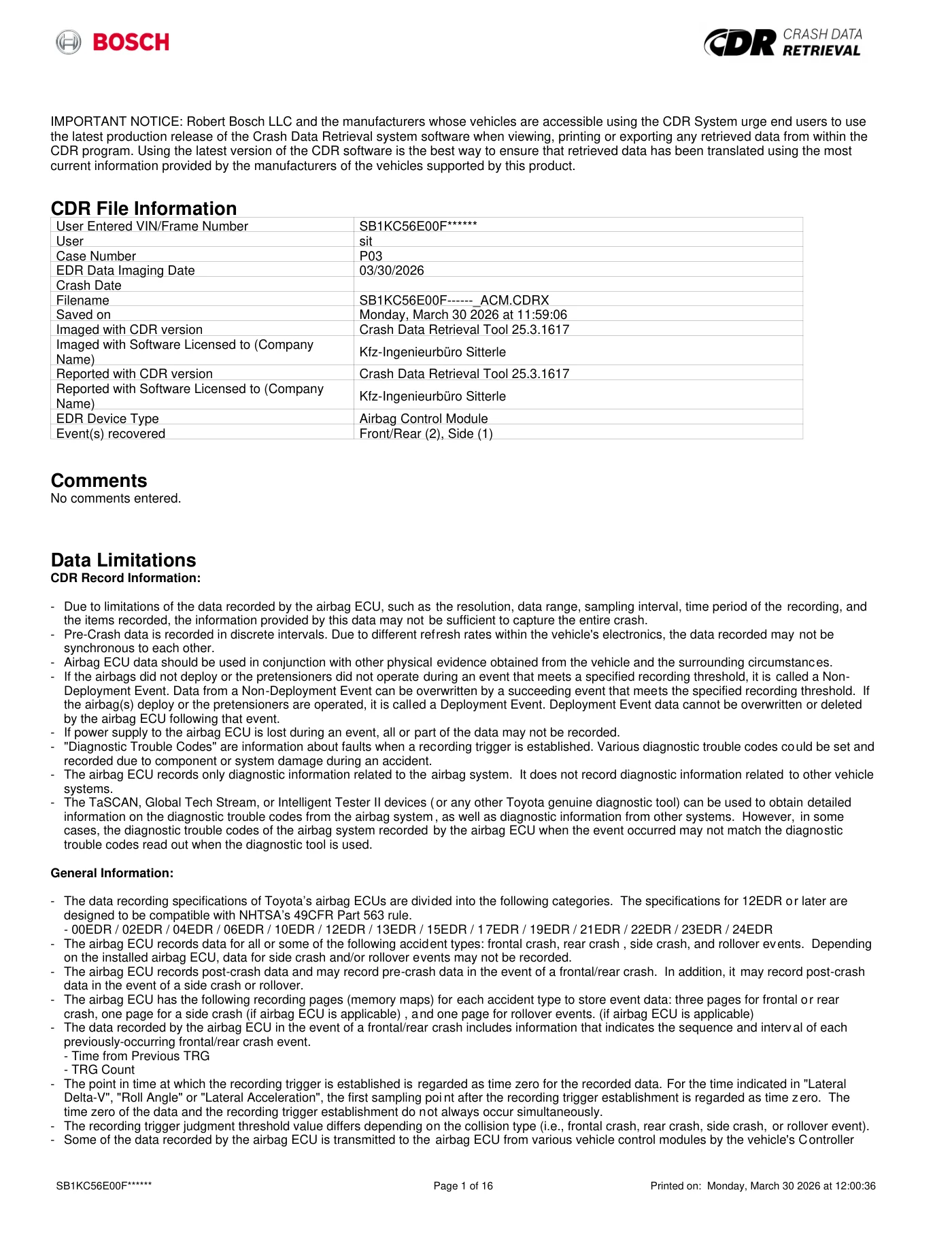
Read page 51 text
IMPORTANT NOTICE: Robert Bosch LLC and the manufacturers whose vehicles are accessible using the CDR System urge end users to use the latest production release of the Crash Data Retrieval system software when viewing, printing or exporting any retrieved data from within the CDR program. Using the latest version of the CDR software is the best way to ensure that retrieved data has been translated using the most current information provided by the manufacturers of the vehicles supported by this product. CDR File Information User Entered VIN/Frame Number SB1KC56E00F****** User sit Case Number P03 EDR Data Imaging Date 03/30/2026 Crash Date Filename SB1KC56E00F------_ACM.CDRX Saved on Monday, March 30 2026 at 11:59:06 Imaged with CDR version Crash Data Retrieval Tool 25.3.1617 Imaged with Software Licensed to (Company Name) Kfz-Ingenieurbüro Sitterle Reported with CDR version Crash Data Retrieval Tool 25.3.1617 Reported with Software Licensed to (Company Name) Kfz-Ingenieurbüro Sitterle EDR Device Type Airbag Control Module Event(s) recovered Front/Rear (2), Side (1) Comments No comments entered. Data Limitations CDR Record Information: - Due to limitations of the data recorded by the airbag ECU, such as the resolution, data range, sampling interval, time period of the recording, and the items recorded, the information provided by this data may not be sufficient to capture the entire crash. - Pre-Crash data is recorded in discrete intervals. Due to different refresh rates within the vehicle's electronics, the data recorded may not be synchronous to each other. - Airbag ECU data should be used in conjunction with other physical evidence obtained from the vehicle and the surrounding circumstances. - If the airbags did not deploy or the pretensioners did not operate during an event that meets a specified recording threshold, it is called a Non- Deployment Event. Data from a Non-Deployment Event can be overwritten by a succeeding event that meets the specified recording threshold. If the airbag(s) deploy or the pretensioners are operated, it is called a Deployment Event. Deployment Event data cannot be overwritten or deleted by the airbag ECU following that event. - If power supply to the airbag ECU is lost during an event, all or part of the data may not be recorded. - "Diagnostic Trouble Codes" are information about faults when a recording trigger is established. Various diagnostic trouble codes could be set and recorded due to component or system damage during an accident. - The airbag ECU records only diagnostic information related to the airbag system. It does not record diagnostic information related to other vehicle systems. - The TaSCAN, Global Tech Stream, or Intelligent Tester II devices (or any other Toyota genuine diagnostic tool) can be used to obtain detailed information on the diagnostic trouble codes from the airbag system, as well as diagnostic information from other systems. However, in some cases, the diagnostic trouble codes of the airbag system recorded by the airbag ECU when the event occurred may not match the diagnostic trouble codes read out when the diagnostic tool is used. General Information: - The data recording specifications of Toyota’s airbag ECUs are divided into the following categories. The specifications for 12EDR or later are designed to be compatible with NHTSA’s 49CFR Part 563 rule. - 00EDR / 02EDR / 04EDR / 06EDR / 10EDR / 12EDR / 13EDR / 15EDR / 17EDR / 19EDR / 21EDR / 22EDR / 23EDR / 24EDR - The airbag ECU records data for all or some of the following accident types: frontal crash, rear crash , side crash, and rollover events. Depending on the installed airbag ECU, data for side crash and/or rollover events may not be recorded. - The airbag ECU records post-crash data and may record pre-crash data in the event of a frontal/rear crash. In addition, it may record post-crash data in the event of a side crash or rollover. - The airbag ECU has the following recording pages (memory maps) for each accident type to store event data: three pages for frontal or rear crash, one page for a side crash (if airbag ECU is applicable) , and one page for rollover events. (if airbag ECU is applicable) - The data recorded by the airbag ECU in the event of a frontal/rear crash includes information that indicates the sequence and interval of each previously-occurring frontal/rear crash event. - Time from Previous TRG - TRG Count - The point in time at which the recording trigger is established is regarded as time zero for the recorded data. For the time indicated in "Lateral Delta-V", "Roll Angle" or "Lateral Acceleration", the first sampling poi nt after the recording trigger establishment is regarded as time zero. The time zero of the data and the recording trigger establishment do not always occur simultaneously. - The recording trigger judgment threshold value differs depending on the collision type (i.e., frontal crash, rear crash, side crash, or rollover event). - Some of the data recorded by the airbag ECU is transmitted to the airbag ECU from various vehicle control modules by the vehicle's Controller SB1KC56E00F****** Page 1 of 16 Printed on: Monday, March 30 2026 at 12:00:36
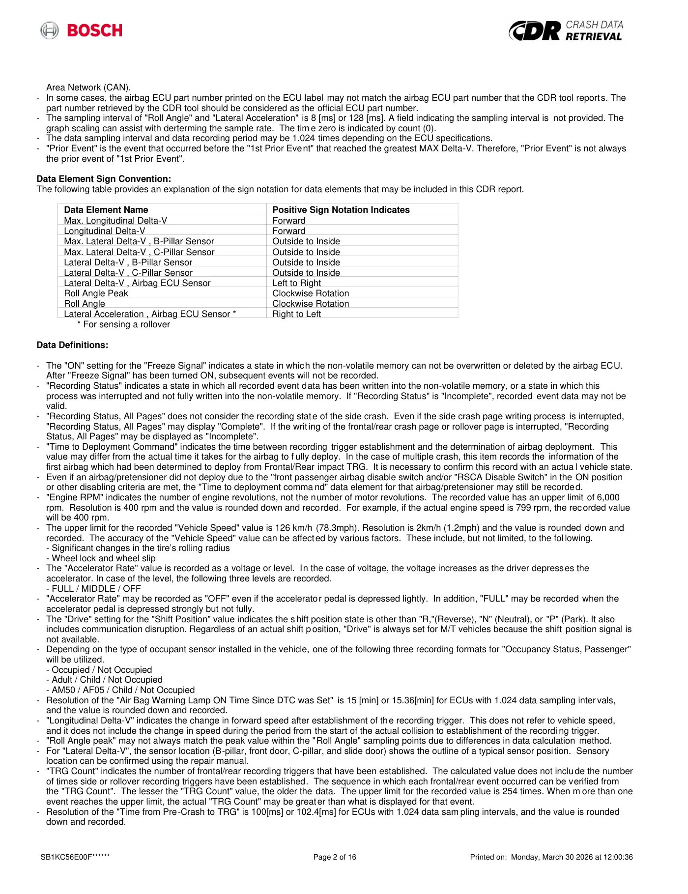
Read page 52 text
Area Network (CAN). - In some cases, the airbag ECU part number printed on the ECU label may not match the airbag ECU part number that the CDR tool reports. The part number retrieved by the CDR tool should be considered as the official ECU part number. - The sampling interval of "Roll Angle" and "Lateral Acceleration" is 8 [ms] or 128 [ms]. A field indicating the sampling interval is not provided. The graph scaling can assist with derterming the sample rate. The tim e zero is indicated by count (0). - The data sampling interval and data recording period may be 1.024 times depending on the ECU specifications. - "Prior Event" is the event that occurred before the "1st Prior Event" that reached the greatest MAX Delta-V. Therefore, "Prior Event" is not always the prior event of "1st Prior Event". Data Element Sign Convention: The following table provides an explanation of the sign notation for data elements that may be included in this CDR report. Data Element Name Positive Sign Notation Indicates Max. Longitudinal Delta-V Forward Longitudinal Delta-V Forward Max. Lateral Delta-V , B-Pillar Sensor Outside to Inside Max. Lateral Delta-V , C-Pillar Sensor Outside to Inside Lateral Delta-V , B-Pillar Sensor Outside to Inside Lateral Delta-V , C-Pillar Sensor Outside to Inside Lateral Delta-V , Airbag ECU Sensor Left to Right Roll Angle Peak Clockwise Rotation Roll Angle Clockwise Rotation Lateral Acceleration , Airbag ECU Sensor * Right to Left * For sensing a rollover Data Definitions: - The "ON" setting for the "Freeze Signal" indicates a state in which the non-volatile memory can not be overwritten or deleted by the airbag ECU. After "Freeze Signal" has been turned ON, subsequent events will not be recorded. - "Recording Status" indicates a state in which all recorded event data has been written into the non-volatile memory, or a state in which this process was interrupted and not fully written into the non-volatile memory. If "Recording Status" is "Incomplete", recorded event data may not be valid. - "Recording Status, All Pages" does not consider the recording state of the side crash. Even if the side crash page writing process is interrupted, "Recording Status, All Pages" may display "Complete". If the writing of the frontal/rear crash page or rollover page is interrupted, "Recording Status, All Pages" may be displayed as "Incomplete". - "Time to Deployment Command" indicates the time between recording trigger establishment and the determination of airbag deployment. This value may differ from the actual time it takes for the airbag to f ully deploy. In the case of multiple crash, this item records the information of the first airbag which had been determined to deploy from Frontal/Rear impact TRG. It is necessary to confirm this record with an actua l vehicle state. - Even if an airbag/pretensioner did not deploy due to the "front passenger airbag disable switch and/or "RSCA Disable Switch" in the ON position or other disabling criteria are met, the "Time to deployment comma nd" data element for that airbag/pretensioner may still be recorded. - "Engine RPM" indicates the number of engine revolutions, not the number of motor revolutions. The recorded value has an upper limit of 6,000 rpm. Resolution is 400 rpm and the value is rounded down and recorded. For example, if the actual engine speed is 799 rpm, the recorded value will be 400 rpm. - The upper limit for the recorded "Vehicle Speed" value is 126 km/h (78.3mph). Resolution is 2km/h (1.2mph) and the value is rounded down and recorded. The accuracy of the "Vehicle Speed" value can be affected by various factors. These include, but not limited, to the fol lowing. - Significant changes in the tire’s rolling radius - Wheel lock and wheel slip - The "Accelerator Rate" value is recorded as a voltage or level. In the case of voltage, the voltage increases as the driver depresses the accelerator. In case of the level, the following three levels are recorded. - FULL / MIDDLE / OFF - "Accelerator Rate" may be recorded as "OFF" even if the accelerator pedal is depressed lightly. In addition, "FULL" may be recorded when the accelerator pedal is depressed strongly but not fully. - The "Drive" setting for the "Shift Position" value indicates the shift position state is other than "R,"(Reverse), "N" (Neutral), or "P" (Park). It also includes communication disruption. Regardless of an actual shift p osition, "Drive" is always set for M/T vehicles because the shift position signal is not available. - Depending on the type of occupant sensor installed in the vehicle, one of the following three recording formats for "Occupancy Status, Passenger" will be utilized. - Occupied / Not Occupied - Adult / Child / Not Occupied - AM50 / AF05 / Child / Not Occupied - Resolution of the "Air Bag Warning Lamp ON Time Since DTC was Set" is 15 [min] or 15.36[min] for ECUs with 1.024 data sampling inter vals, and the value is rounded down and recorded. - "Longitudinal Delta-V" indicates the change in forward speed after establishment of the recording trigger. This does not refer to vehicle speed, and it does not include the change in speed during the period from the start of the actual collision to establishment of the recordi ng trigger. - "Roll Angle peak" may not always match the peak value within the "Roll Angle" sampling points due to differences in data calculation method. - For "Lateral Delta-V", the sensor location (B-pillar, front door, C-pillar, and slide door) shows the outline of a typical sensor position. Sensory location can be confirmed using the repair manual. - "TRG Count" indicates the number of frontal/rear recording triggers that have been established. The calculated value does not include the number of times side or rollover recording triggers have been established. The sequence in which each frontal/rear event occurred can be verified from the "TRG Count". The lesser the "TRG Count" value, the older the data. The upper limit for the recorded value is 254 times. When m ore than one event reaches the upper limit, the actual "TRG Count" may be greater than what is displayed for that event. - Resolution of the "Time from Pre-Crash to TRG" is 100[ms] or 102.4[ms] for ECUs with 1.024 data sam pling intervals, and the value is rounded down and recorded. SB1KC56E00F****** Page 2 of 16 Printed on: Monday, March 30 2026 at 12:00:36

Read page 53 text
- For "Time from Previous TRG", the recording trigger of side crash and rollover is not considered. The upper limit for the recorded value is 5000 [ms] or 5120 [ms] for ECUs with 1.024 data sampling intervals. Re solution is 20 [ms] or 20.48 [ms] and the value is rounded down and recorded. - If 2 or more frontal/rear events occur successively within a period of 5000ms (or 5120ms for ECUs with 1.024 data sampling intervals), the actual sample time before the trigger is not displayed for subsequent events. The sample time before trigger will only be displayed for the first event of the successive events. For subsequent events (i.e second event or later events), the pre-crash "Time (sec)" data is replaced by integers -5 through -1 and the heading "Time (sec)" is replaced with "Sample Count". The time between "Sample Count" integers (-5 through -1) cannot be determined. The time between the last integer and TRG cannot be determined. - "Pre-Crash Data Status" indicates data communication status of the vehi cle. If communication disruption or other failure is occur, "Inval id" is set. Moreover, "Invalid" is set for some M/T vehicles because the shift position signal is not transmitted for them even if the other dat a is valid. 05002_ToyotaTRW_r043 SB1KC56E00F****** Page 3 of 16 Printed on: Monday, March 30 2026 at 12:00:36
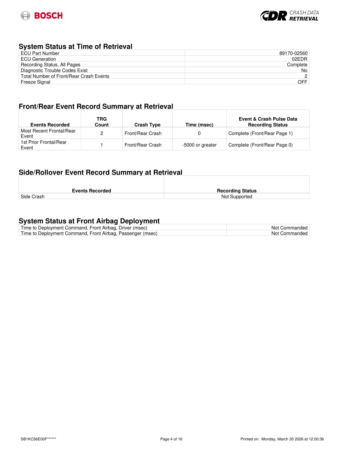
Read page 54 text
System Status at Time of Retrieval ECU Part Number 89170-02560 ECU Generation 02EDR Recording Status, All Pages Complete Diagnostic Trouble Codes Exist No Total Number of Front/Rear Crash Events 2 Freeze Signal OFF Front/Rear Event Record Summary at Retrieval Events Recorded TRG Count Crash Type Time (msec) Event & Crash Pulse Data Recording Status Most Recent Frontal/Rear Event 2 Front/Rear Crash 0 Complete (Front/Rear Page 1) 1st Prior Frontal/Rear Event 1 Front/Rear Crash -5000 or greater Complete (Front/Rear Page 0) Side/Rollover Event Record Summary at Retrieval Events Recorded Recording Status Side Crash Not Supported System Status at Front Airbag Deployment Time to Deployment Command, Front Airbag, Driver (msec) Not Commanded Time to Deployment Command, Front Airbag, Passenger (msec) Not Commanded SB1KC56E00F****** Page 4 of 16 Printed on: Monday, March 30 2026 at 12:00:36
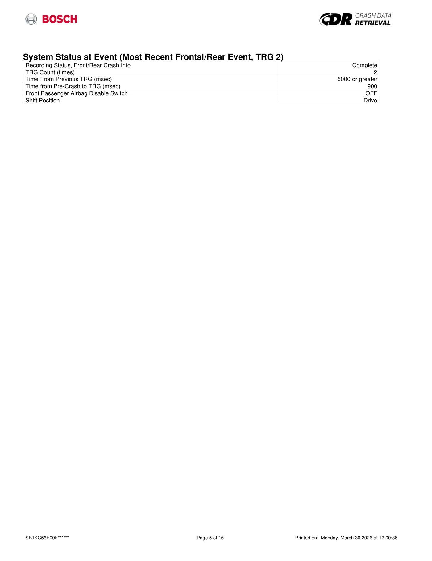
Read page 55 text
System Status at Event (Most Recent Frontal/Rear Event, TRG 2) Recording Status, Front/Rear Crash Info. Complete TRG Count (times) 2 Time From Previous TRG (msec) 5000 or greater Time from Pre-Crash to TRG (msec) 900 Front Passenger Airbag Disable Switch OFF Shift Position Drive SB1KC56E00F****** Page 5 of 16 Printed on: Monday, March 30 2026 at 12:00:36
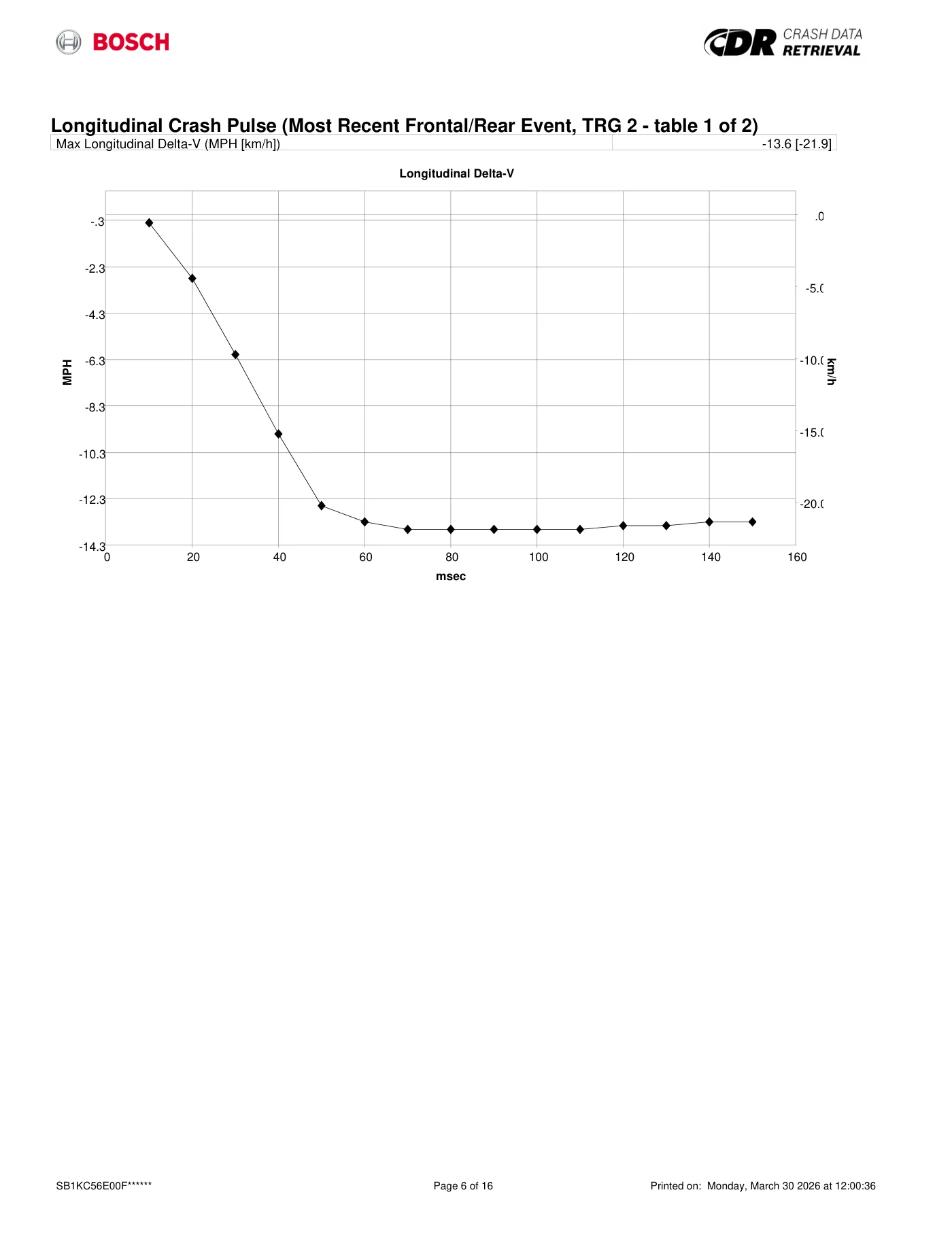
Read page 56 text
Longitudinal Crash Pulse (Most Recent Frontal/Rear Event, TRG 2 - table 1 of 2) Max Longitudinal Delta-V (MPH [km/h]) -13.6 [-21.9] -14.3 -12.3 -10.3 -8.3 -6.3 -4.3 -2.3 -.3 .0 -5.0 -10.0 -15.0 -20.0 0 20 40 60 80 100 120 140 160 MPH km/h Longitudinal Delta-V Longitudinal Delta-V msec SB1KC56E00F****** Page 6 of 16 Printed on: Monday, March 30 2026 at 12:00:36
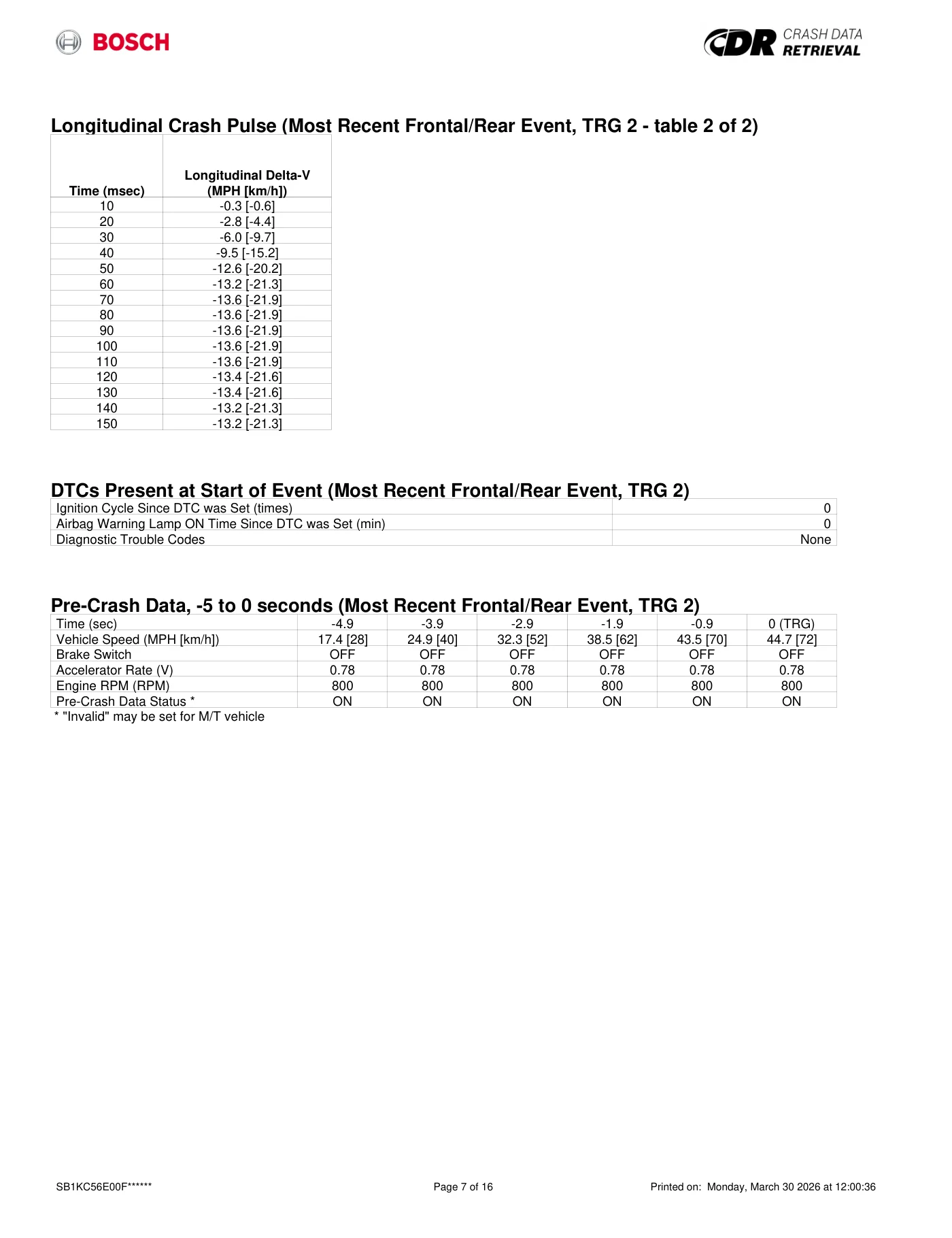
Read page 57 text
Longitudinal Crash Pulse (Most Recent Frontal/Rear Event, TRG 2 - table 2 of 2) Time (msec) Longitudinal Delta-V (MPH [km/h]) 10 -0.3 [-0.6] 20 -2.8 [-4.4] 30 -6.0 [-9.7] 40 -9.5 [-15.2] 50 -12.6 [-20.2] 60 -13.2 [-21.3] 70 -13.6 [-21.9] 80 -13.6 [-21.9] 90 -13.6 [-21.9] 100 -13.6 [-21.9] 110 -13.6 [-21.9] 120 -13.4 [-21.6] 130 -13.4 [-21.6] 140 -13.2 [-21.3] 150 -13.2 [-21.3] DTCs Present at Start of Event (Most Recent Frontal/Rear Event, TRG 2) Ignition Cycle Since DTC was Set (times) 0 Airbag Warning Lamp ON Time Since DTC was Set (min) 0 Diagnostic Trouble Codes None Pre-Crash Data, -5 to 0 seconds (Most Recent Frontal/Rear Event, TRG 2) Time (sec) -4.9 -3.9 -2.9 -1.9 -0.9 0 (TRG) Vehicle Speed (MPH [km/h]) 17.4 [28] 24.9 [40] 32.3 [52] 38.5 [62] 43.5 [70] 44.7 [72] Brake Switch OFF OFF OFF OFF OFF OFF Accelerator Rate (V) 0.78 0.78 0.78 0.78 0.78 0.78 Engine RPM (RPM) 800 800 800 800 800 800 Pre-Crash Data Status * ON ON ON ON ON ON * "Invalid" may be set for M/T vehicle SB1KC56E00F****** Page 7 of 16 Printed on: Monday, March 30 2026 at 12:00:36
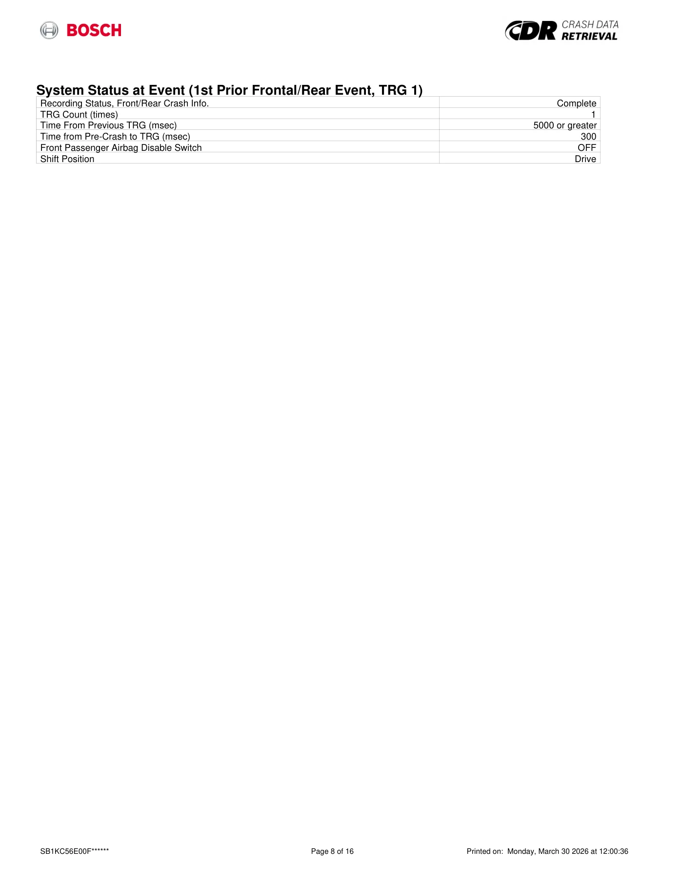
Read page 58 text
System Status at Event (1st Prior Frontal/Rear Event, TRG 1) Recording Status, Front/Rear Crash Info. Complete TRG Count (times) 1 Time From Previous TRG (msec) 5000 or greater Time from Pre-Crash to TRG (msec) 300 Front Passenger Airbag Disable Switch OFF Shift Position Drive SB1KC56E00F****** Page 8 of 16 Printed on: Monday, March 30 2026 at 12:00:36
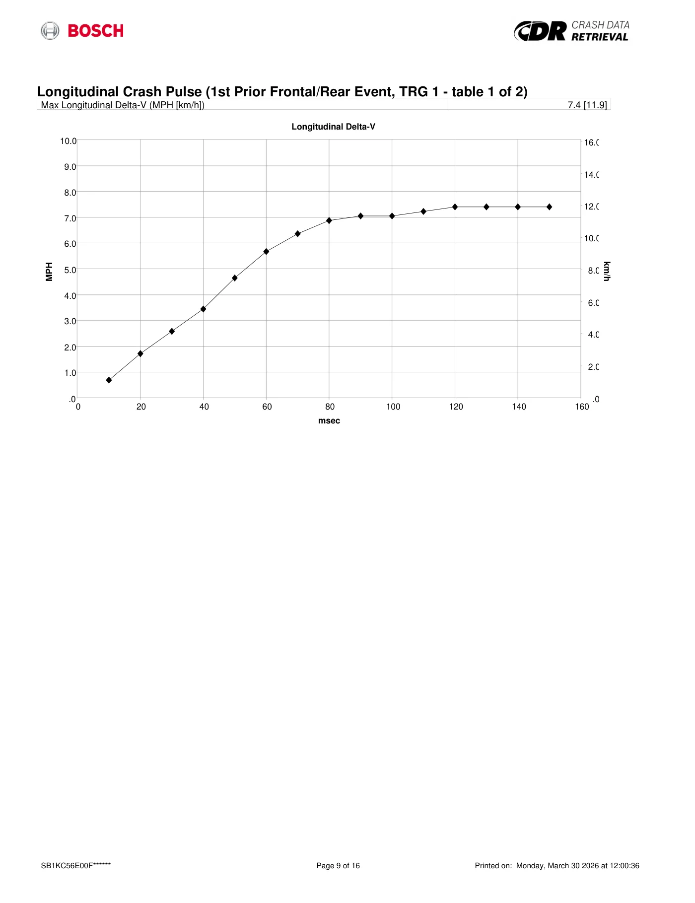
Read page 59 text
Longitudinal Crash Pulse (1st Prior Frontal/Rear Event, TRG 1 - table 1 of 2) Max Longitudinal Delta-V (MPH [km/h]) 7.4 [11.9] .0 1.0 2.0 3.0 4.0 5.0 6.0 7.0 8.0 9.0 10.0 .0 2.0 4.0 6.0 8.0 10.0 12.0 14.0 16.0 0 20 40 60 80 100 120 140 160 MPH km/h Longitudinal Delta-V Longitudinal Delta-V msec SB1KC56E00F****** Page 9 of 16 Printed on: Monday, March 30 2026 at 12:00:36
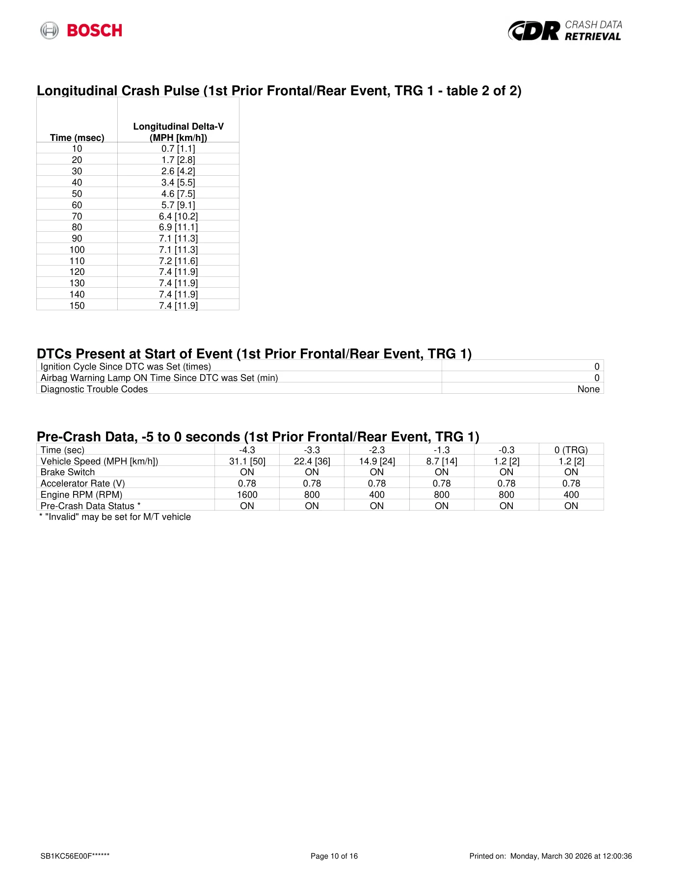
Read page 60 text
Longitudinal Crash Pulse (1st Prior Frontal/Rear Event, TRG 1 - table 2 of 2) Time (msec) Longitudinal Delta-V (MPH [km/h]) 10 0.7 [1.1] 20 1.7 [2.8] 30 2.6 [4.2] 40 3.4 [5.5] 50 4.6 [7.5] 60 5.7 [9.1] 70 6.4 [10.2] 80 6.9 [11.1] 90 7.1 [11.3] 100 7.1 [11.3] 110 7.2 [11.6] 120 7.4 [11.9] 130 7.4 [11.9] 140 7.4 [11.9] 150 7.4 [11.9] DTCs Present at Start of Event (1st Prior Frontal/Rear Event, TRG 1) Ignition Cycle Since DTC was Set (times) 0 Airbag Warning Lamp ON Time Since DTC was Set (min) 0 Diagnostic Trouble Codes None Pre-Crash Data, -5 to 0 seconds (1st Prior Frontal/Rear Event, TRG 1) Time (sec) -4.3 -3.3 -2.3 -1.3 -0.3 0 (TRG) Vehicle Speed (MPH [km/h]) 31.1 [50] 22.4 [36] 14.9 [24] 8.7 [14] 1.2 [2] 1.2 [2] Brake Switch ON ON ON ON ON ON Accelerator Rate (V) 0.78 0.78 0.78 0.78 0.78 0.78 Engine RPM (RPM) 1600 800 400 800 800 400 Pre-Crash Data Status * ON ON ON ON ON ON * "Invalid" may be set for M/T vehicle SB1KC56E00F****** Page 10 of 16 Printed on: Monday, March 30 2026 at 12:00:36
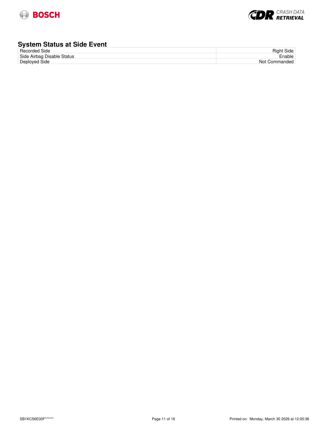
Read page 61 text
System Status at Side Event Recorded Side Right Side Side Airbag Disable Status Enable Deployed Side Not Commanded SB1KC56E00F****** Page 11 of 16 Printed on: Monday, March 30 2026 at 12:00:36
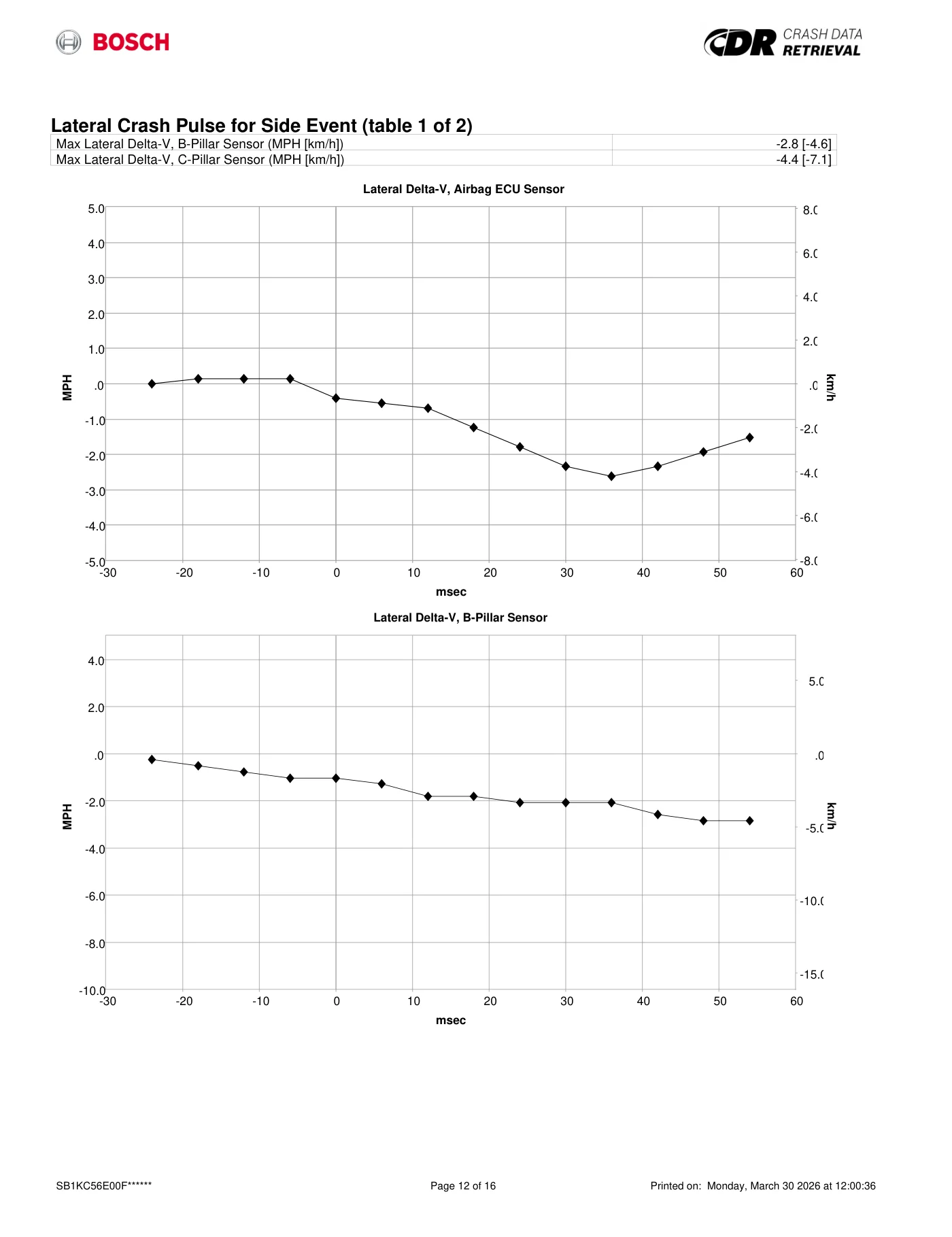
Read page 62 text
Lateral Crash Pulse for Side Event (table 1 of 2) Max Lateral Delta-V, B-Pillar Sensor (MPH [km/h]) -2.8 [-4.6] Max Lateral Delta-V, C-Pillar Sensor (MPH [km/h]) -4.4 [-7.1] -5.0 -4.0 -3.0 -2.0 -1.0 .0 1.0 2.0 3.0 4.0 5.0 .0 2.0 4.0 6.0 8.0 -2.0 -4.0 -6.0 -8.0 0 10 20 30 40 50 60 -10 -20 -30 MPH km/h Lateral Delta-V, Airbag ECU Sensor Lateral Delta-V, Airbag ECU Sensor msec -10.0 -8.0 -6.0 -4.0 -2.0 .0 2.0 4.0 .0 5.0 -5.0 -10.0 -15.0 0 10 20 30 40 50 60 -10 -20 -30 MPH km/h Lateral Delta-V, B-Pillar Sensor Lateral Delta-V, B-Pillar Sensor msec SB1KC56E00F****** Page 12 of 16 Printed on: Monday, March 30 2026 at 12:00:36
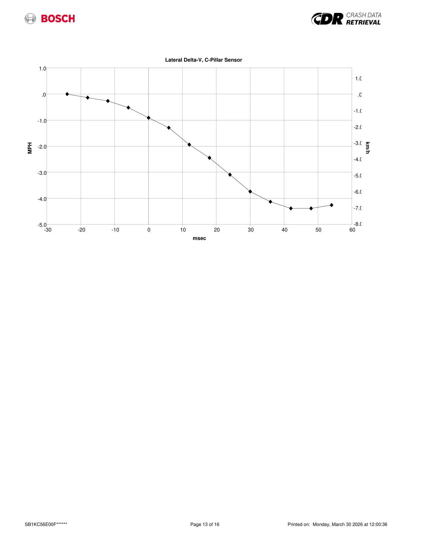
Read page 63 text
-5.0 -4.0 -3.0 -2.0 -1.0 .0 1.0 .0 1.0 -1.0 -2.0 -3.0 -4.0 -5.0 -6.0 -7.0 -8.0 0 10 20 30 40 50 60 -10 -20 -30 MPH km/h Lateral Delta-V, C-Pillar Sensor Lateral Delta-V, C-Pillar Sensor msec SB1KC56E00F****** Page 13 of 16 Printed on: Monday, March 30 2026 at 12:00:36
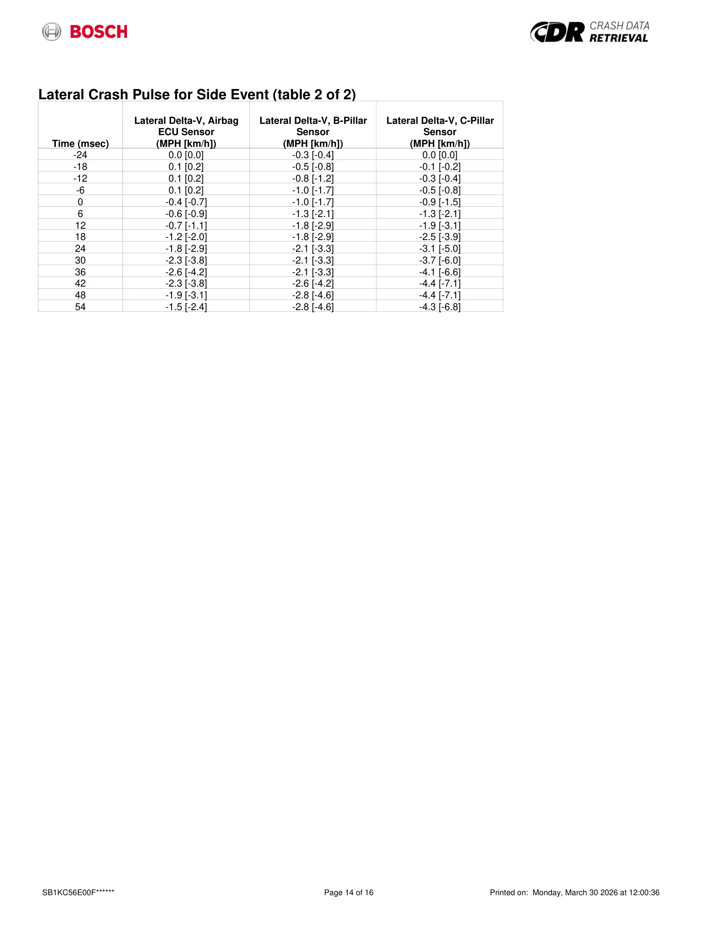
Read page 64 text
Lateral Crash Pulse for Side Event (table 2 of 2) Time (msec) Lateral Delta-V, Airbag ECU Sensor (MPH [km/h]) Lateral Delta-V, B-Pillar Sensor (MPH [km/h]) Lateral Delta-V, C-Pillar Sensor (MPH [km/h]) -24 0.0 [0.0] -0.3 [-0.4] 0.0 [0.0] -18 0.1 [0.2] -0.5 [-0.8] -0.1 [-0.2] -12 0.1 [0.2] -0.8 [-1.2] -0.3 [-0.4] -6 0.1 [0.2] -1.0 [-1.7] -0.5 [-0.8] 0 -0.4 [-0.7] -1.0 [-1.7] -0.9 [-1.5] 6 -0.6 [-0.9] -1.3 [-2.1] -1.3 [-2.1] 12 -0.7 [-1.1] -1.8 [-2.9] -1.9 [-3.1] 18 -1.2 [-2.0] -1.8 [-2.9] -2.5 [-3.9] 24 -1.8 [-2.9] -2.1 [-3.3] -3.1 [-5.0] 30 -2.3 [-3.8] -2.1 [-3.3] -3.7 [-6.0] 36 -2.6 [-4.2] -2.1 [-3.3] -4.1 [-6.6] 42 -2.3 [-3.8] -2.6 [-4.2] -4.4 [-7.1] 48 -1.9 [-3.1] -2.8 [-4.6] -4.4 [-7.1] 54 -1.5 [-2.4] -2.8 [-4.6] -4.3 [-6.8] SB1KC56E00F****** Page 14 of 16 Printed on: Monday, March 30 2026 at 12:00:36
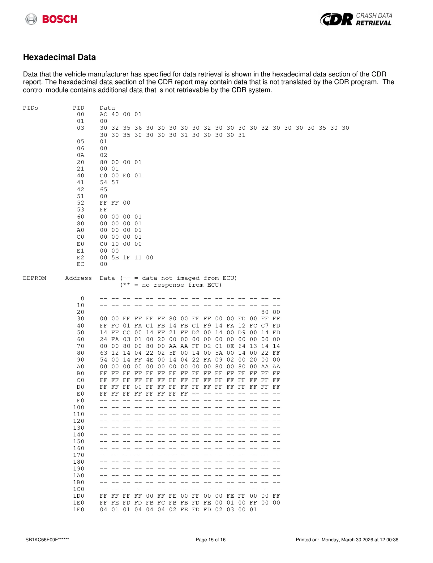
Read page 65 text
Hexadecimal Data Data that the vehicle manufacturer has specified for data retrieval is shown in the hexadecimal data section of the CDR report. The hexadecimal data section of the CDR report may contain data that is not translated by the CDR program. The control module contains additional data that is not retrievable by the CDR system. PIDs PID Data 00 AC 40 00 01 01 00 03 30 32 35 36 30 30 30 30 30 32 30 30 30 30 32 30 30 30 30 35 30 30 30 30 35 30 30 30 30 31 30 30 30 30 31 05 01 06 00 0A 02 20 80 00 00 01 21 00 01 40 C0 00 E0 01 41 54 57 42 65 51 00 52 FF FF 00 53 FF 60 00 00 00 01 80 00 00 00 01 A0 00 00 00 01 C0 00 00 00 01 E0 C0 10 00 00 E1 00 00 E2 00 5B 1F 11 00 EC 00 EEPROM Address Data (-- = data not imaged from ECU) (** = no response from ECU) 0 -- -- -- -- -- -- -- -- -- -- -- -- -- -- -- -- 10 -- -- -- -- -- -- -- -- -- -- -- -- -- -- -- -- 20 -- -- -- -- -- -- -- -- -- -- -- -- -- -- 80 00 30 00 00 FF FF FF FF 80 00 FF FF 00 00 FD 00 FF FF 40 FF FC 01 FA C1 FB 14 FB C1 F9 14 FA 12 FC C7 FD 50 14 FF CC 00 14 FF 21 FF D2 00 14 00 D9 00 14 FD 60 24 FA 03 01 00 20 00 00 00 00 00 00 00 00 00 00 70 00 00 80 00 80 00 AA AA FF 02 01 0E 64 13 14 14 80 63 12 14 04 22 02 5F 00 14 00 5A 00 14 00 22 FF 90 54 00 14 FF 4E 00 14 04 22 FA 09 02 00 20 00 00 A0 00 00 00 00 00 00 00 00 00 00 80 00 80 00 AA AA B0 FF FF FF FF FF FF FF FF FF FF FF FF FF FF FF FF C0 FF FF FF FF FF FF FF FF FF FF FF FF FF FF FF FF D0 FF FF FF 00 FF FF FF FF FF FF FF FF FF FF FF FF E0 FF FF FF FF FF FF FF FF -- -- -- -- -- -- -- -- F0 -- -- -- -- -- -- -- -- -- -- -- -- -- -- -- -- 100 -- -- -- -- -- -- -- -- -- -- -- -- -- -- -- -- 110 -- -- -- -- -- -- -- -- -- -- -- -- -- -- -- -- 120 -- -- -- -- -- -- -- -- -- -- -- -- -- -- -- -- 130 -- -- -- -- -- -- -- -- -- -- -- -- -- -- -- -- 140 -- -- -- -- -- -- -- -- -- -- -- -- -- -- -- -- 150 -- -- -- -- -- -- -- -- -- -- -- -- -- -- -- -- 160 -- -- -- -- -- -- -- -- -- -- -- -- -- -- -- -- 170 -- -- -- -- -- -- -- -- -- -- -- -- -- -- -- -- 180 -- -- -- -- -- -- -- -- -- -- -- -- -- -- -- -- 190 -- -- -- -- -- -- -- -- -- -- -- -- -- -- -- -- 1A0 -- -- -- -- -- -- -- -- -- -- -- -- -- -- -- -- 1B0 -- -- -- -- -- -- -- -- -- -- -- -- -- -- -- -- 1C0 -- -- -- -- -- -- -- -- -- -- -- -- -- -- -- -- 1D0 FF FF FF FF 00 FF FE 00 FF 00 00 FE FF 00 00 FF 1E0 FF FE FD FD FB FC FB FB FD FE 00 01 00 FF 00 00 1F0 04 01 01 04 04 04 02 FE FD FD 02 03 00 01 SB1KC56E00F****** Page 15 of 16 Printed on: Monday, March 30 2026 at 12:00:36

Read page 66 text
Disclaimer of Liability The users of the CDR product and reviewers of the CDR reports and exported data shall ensure that data and information supplied is applicable to the vehicle, vehicle's system(s) and the vehicle ECU. Robert Bosch LLC and all its directors, officers, employees and members shall not be liable for damages arising out of or related to incorrect, incomplete or misinterpreted software and/or data. Robert Bosch LLC expressly excludes all liability for incidental, consequential, special or punitive damages arising from or related to the CDR data, CDR software or use thereof. SB1KC56E00F****** Page 16 of 16 Printed on: Monday, March 30 2026 at 12:00:36
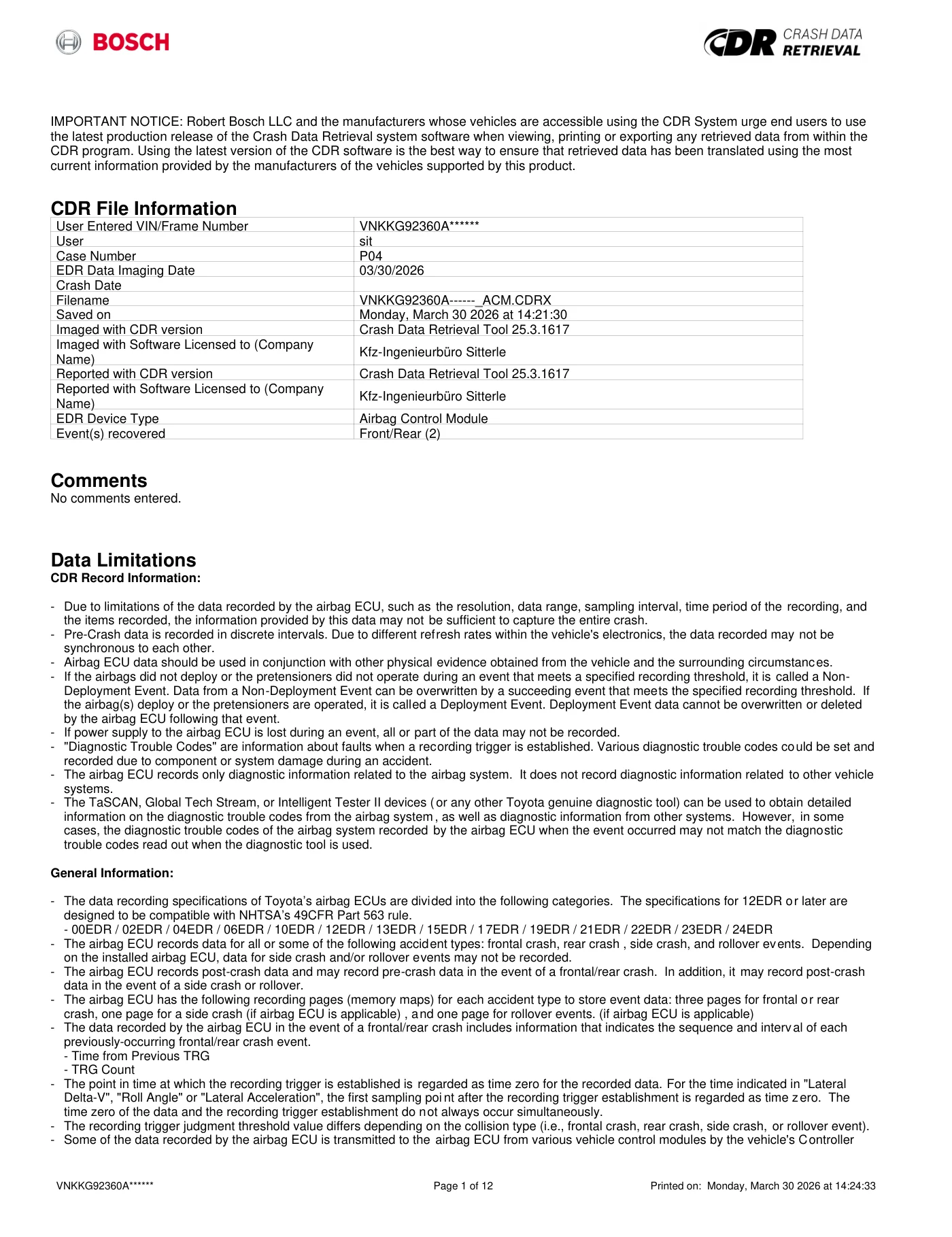
Read page 67 text
IMPORTANT NOTICE: Robert Bosch LLC and the manufacturers whose vehicles are accessible using the CDR System urge end users to use the latest production release of the Crash Data Retrieval system software when viewing, printing or exporting any retrieved data from within the CDR program. Using the latest version of the CDR software is the best way to ensure that retrieved data has been translated using the most current information provided by the manufacturers of the vehicles supported by this product. CDR File Information User Entered VIN/Frame Number VNKKG92360A****** User sit Case Number P04 EDR Data Imaging Date 03/30/2026 Crash Date Filename VNKKG92360A------_ACM.CDRX Saved on Monday, March 30 2026 at 14:21:30 Imaged with CDR version Crash Data Retrieval Tool 25.3.1617 Imaged with Software Licensed to (Company Name) Kfz-Ingenieurbüro Sitterle Reported with CDR version Crash Data Retrieval Tool 25.3.1617 Reported with Software Licensed to (Company Name) Kfz-Ingenieurbüro Sitterle EDR Device Type Airbag Control Module Event(s) recovered Front/Rear (2) Comments No comments entered. Data Limitations CDR Record Information: - Due to limitations of the data recorded by the airbag ECU, such as the resolution, data range, sampling interval, time period of the recording, and the items recorded, the information provided by this data may not be sufficient to capture the entire crash. - Pre-Crash data is recorded in discrete intervals. Due to different refresh rates within the vehicle's electronics, the data recorded may not be synchronous to each other. - Airbag ECU data should be used in conjunction with other physical evidence obtained from the vehicle and the surrounding circumstances. - If the airbags did not deploy or the pretensioners did not operate during an event that meets a specified recording threshold, it is called a Non- Deployment Event. Data from a Non-Deployment Event can be overwritten by a succeeding event that meets the specified recording threshold. If the airbag(s) deploy or the pretensioners are operated, it is called a Deployment Event. Deployment Event data cannot be overwritten or deleted by the airbag ECU following that event. - If power supply to the airbag ECU is lost during an event, all or part of the data may not be recorded. - "Diagnostic Trouble Codes" are information about faults when a recording trigger is established. Various diagnostic trouble codes could be set and recorded due to component or system damage during an accident. - The airbag ECU records only diagnostic information related to the airbag system. It does not record diagnostic information related to other vehicle systems. - The TaSCAN, Global Tech Stream, or Intelligent Tester II devices (or any other Toyota genuine diagnostic tool) can be used to obtain detailed information on the diagnostic trouble codes from the airbag system, as well as diagnostic information from other systems. However, in some cases, the diagnostic trouble codes of the airbag system recorded by the airbag ECU when the event occurred may not match the diagnostic trouble codes read out when the diagnostic tool is used. General Information: - The data recording specifications of Toyota’s airbag ECUs are divided into the following categories. The specifications for 12EDR or later are designed to be compatible with NHTSA’s 49CFR Part 563 rule. - 00EDR / 02EDR / 04EDR / 06EDR / 10EDR / 12EDR / 13EDR / 15EDR / 17EDR / 19EDR / 21EDR / 22EDR / 23EDR / 24EDR - The airbag ECU records data for all or some of the following accident types: frontal crash, rear crash , side crash, and rollover events. Depending on the installed airbag ECU, data for side crash and/or rollover events may not be recorded. - The airbag ECU records post-crash data and may record pre-crash data in the event of a frontal/rear crash. In addition, it may record post-crash data in the event of a side crash or rollover. - The airbag ECU has the following recording pages (memory maps) for each accident type to store event data: three pages for frontal or rear crash, one page for a side crash (if airbag ECU is applicable) , and one page for rollover events. (if airbag ECU is applicable) - The data recorded by the airbag ECU in the event of a frontal/rear crash includes information that indicates the sequence and interval of each previously-occurring frontal/rear crash event. - Time from Previous TRG - TRG Count - The point in time at which the recording trigger is established is regarded as time zero for the recorded data. For the time indicated in "Lateral Delta-V", "Roll Angle" or "Lateral Acceleration", the first sampling poi nt after the recording trigger establishment is regarded as time zero. The time zero of the data and the recording trigger establishment do not always occur simultaneously. - The recording trigger judgment threshold value differs depending on the collision type (i.e., frontal crash, rear crash, side crash, or rollover event). - Some of the data recorded by the airbag ECU is transmitted to the airbag ECU from various vehicle control modules by the vehicle's Controller VNKKG92360A****** Page 1 of 12 Printed on: Monday, March 30 2026 at 14:24:33
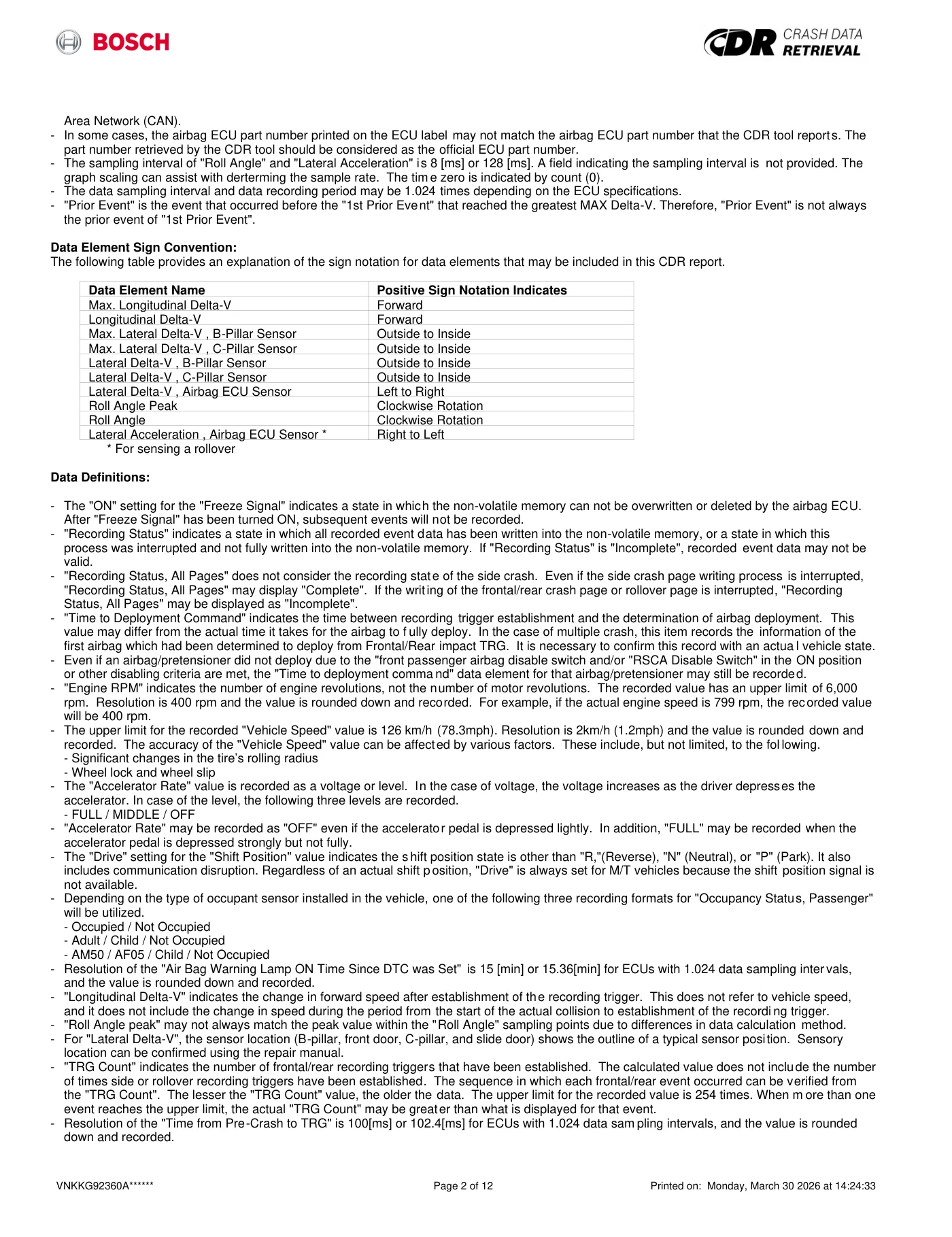
Read page 68 text
Area Network (CAN). - In some cases, the airbag ECU part number printed on the ECU label may not match the airbag ECU part number that the CDR tool reports. The part number retrieved by the CDR tool should be considered as the official ECU part number. - The sampling interval of "Roll Angle" and "Lateral Acceleration" is 8 [ms] or 128 [ms]. A field indicating the sampling interval is not provided. The graph scaling can assist with derterming the sample rate. The tim e zero is indicated by count (0). - The data sampling interval and data recording period may be 1.024 times depending on the ECU specifications. - "Prior Event" is the event that occurred before the "1st Prior Event" that reached the greatest MAX Delta-V. Therefore, "Prior Event" is not always the prior event of "1st Prior Event". Data Element Sign Convention: The following table provides an explanation of the sign notation for data elements that may be included in this CDR report. Data Element Name Positive Sign Notation Indicates Max. Longitudinal Delta-V Forward Longitudinal Delta-V Forward Max. Lateral Delta-V , B-Pillar Sensor Outside to Inside Max. Lateral Delta-V , C-Pillar Sensor Outside to Inside Lateral Delta-V , B-Pillar Sensor Outside to Inside Lateral Delta-V , C-Pillar Sensor Outside to Inside Lateral Delta-V , Airbag ECU Sensor Left to Right Roll Angle Peak Clockwise Rotation Roll Angle Clockwise Rotation Lateral Acceleration , Airbag ECU Sensor * Right to Left * For sensing a rollover Data Definitions: - The "ON" setting for the "Freeze Signal" indicates a state in which the non-volatile memory can not be overwritten or deleted by the airbag ECU. After "Freeze Signal" has been turned ON, subsequent events will not be recorded. - "Recording Status" indicates a state in which all recorded event data has been written into the non-volatile memory, or a state in which this process was interrupted and not fully written into the non-volatile memory. If "Recording Status" is "Incomplete", recorded event data may not be valid. - "Recording Status, All Pages" does not consider the recording state of the side crash. Even if the side crash page writing process is interrupted, "Recording Status, All Pages" may display "Complete". If the writing of the frontal/rear crash page or rollover page is interrupted, "Recording Status, All Pages" may be displayed as "Incomplete". - "Time to Deployment Command" indicates the time between recording trigger establishment and the determination of airbag deployment. This value may differ from the actual time it takes for the airbag to f ully deploy. In the case of multiple crash, this item records the information of the first airbag which had been determined to deploy from Frontal/Rear impact TRG. It is necessary to confirm this record with an actua l vehicle state. - Even if an airbag/pretensioner did not deploy due to the "front passenger airbag disable switch and/or "RSCA Disable Switch" in the ON position or other disabling criteria are met, the "Time to deployment comma nd" data element for that airbag/pretensioner may still be recorded. - "Engine RPM" indicates the number of engine revolutions, not the number of motor revolutions. The recorded value has an upper limit of 6,000 rpm. Resolution is 400 rpm and the value is rounded down and recorded. For example, if the actual engine speed is 799 rpm, the recorded value will be 400 rpm. - The upper limit for the recorded "Vehicle Speed" value is 126 km/h (78.3mph). Resolution is 2km/h (1.2mph) and the value is rounded down and recorded. The accuracy of the "Vehicle Speed" value can be affected by various factors. These include, but not limited, to the fol lowing. - Significant changes in the tire’s rolling radius - Wheel lock and wheel slip - The "Accelerator Rate" value is recorded as a voltage or level. In the case of voltage, the voltage increases as the driver depresses the accelerator. In case of the level, the following three levels are recorded. - FULL / MIDDLE / OFF - "Accelerator Rate" may be recorded as "OFF" even if the accelerator pedal is depressed lightly. In addition, "FULL" may be recorded when the accelerator pedal is depressed strongly but not fully. - The "Drive" setting for the "Shift Position" value indicates the shift position state is other than "R,"(Reverse), "N" (Neutral), or "P" (Park). It also includes communication disruption. Regardless of an actual shift p osition, "Drive" is always set for M/T vehicles because the shift position signal is not available. - Depending on the type of occupant sensor installed in the vehicle, one of the following three recording formats for "Occupancy Status, Passenger" will be utilized. - Occupied / Not Occupied - Adult / Child / Not Occupied - AM50 / AF05 / Child / Not Occupied - Resolution of the "Air Bag Warning Lamp ON Time Since DTC was Set" is 15 [min] or 15.36[min] for ECUs with 1.024 data sampling inter vals, and the value is rounded down and recorded. - "Longitudinal Delta-V" indicates the change in forward speed after establishment of the recording trigger. This does not refer to vehicle speed, and it does not include the change in speed during the period from the start of the actual collision to establishment of the recordi ng trigger. - "Roll Angle peak" may not always match the peak value within the "Roll Angle" sampling points due to differences in data calculation method. - For "Lateral Delta-V", the sensor location (B-pillar, front door, C-pillar, and slide door) shows the outline of a typical sensor position. Sensory location can be confirmed using the repair manual. - "TRG Count" indicates the number of frontal/rear recording triggers that have been established. The calculated value does not include the number of times side or rollover recording triggers have been established. The sequence in which each frontal/rear event occurred can be verified from the "TRG Count". The lesser the "TRG Count" value, the older the data. The upper limit for the recorded value is 254 times. When m ore than one event reaches the upper limit, the actual "TRG Count" may be greater than what is displayed for that event. - Resolution of the "Time from Pre-Crash to TRG" is 100[ms] or 102.4[ms] for ECUs with 1.024 data sam pling intervals, and the value is rounded down and recorded. VNKKG92360A****** Page 2 of 12 Printed on: Monday, March 30 2026 at 14:24:33

Read page 69 text
- For "Time from Previous TRG", the recording trigger of side crash and rollover is not considered. The upper limit for the recorded value is 5000 [ms] or 5120 [ms] for ECUs with 1.024 data sampling intervals. Re solution is 20 [ms] or 20.48 [ms] and the value is rounded down and recorded. - If 2 or more frontal/rear events occur successively within a period of 5000ms (or 5120ms for ECUs with 1.024 data sampling intervals), the actual sample time before the trigger is not displayed for subsequent events. The sample time before trigger will only be displayed for the first event of the successive events. For subsequent events (i.e second event or later events), the pre-crash "Time (sec)" data is replaced by integers -5 through -1 and the heading "Time (sec)" is replaced with "Sample Count". The time between "Sample Count" integers (-5 through -1) cannot be determined. The time between the last integer and TRG cannot be determined. - "Pre-Crash Data Status" indicates data communication status of the vehi cle. If communication disruption or other failure is occur, "Inval id" is set. Moreover, "Invalid" is set for some M/T vehicles because the shift position signal is not transmitted for them even if the other dat a is valid. 05002_ToyotaTRW_r043 VNKKG92360A****** Page 3 of 12 Printed on: Monday, March 30 2026 at 14:24:33
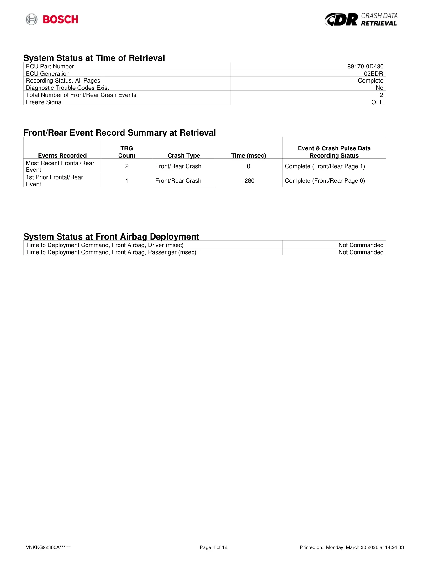
Read page 70 text
System Status at Time of Retrieval ECU Part Number 89170-0D430 ECU Generation 02EDR Recording Status, All Pages Complete Diagnostic Trouble Codes Exist No Total Number of Front/Rear Crash Events 2 Freeze Signal OFF Front/Rear Event Record Summary at Retrieval Events Recorded TRG Count Crash Type Time (msec) Event & Crash Pulse Data Recording Status Most Recent Frontal/Rear Event 2 Front/Rear Crash 0 Complete (Front/Rear Page 1) 1st Prior Frontal/Rear Event 1 Front/Rear Crash -280 Complete (Front/Rear Page 0) System Status at Front Airbag Deployment Time to Deployment Command, Front Airbag, Driver (msec) Not Commanded Time to Deployment Command, Front Airbag, Passenger (msec) Not Commanded VNKKG92360A****** Page 4 of 12 Printed on: Monday, March 30 2026 at 14:24:33
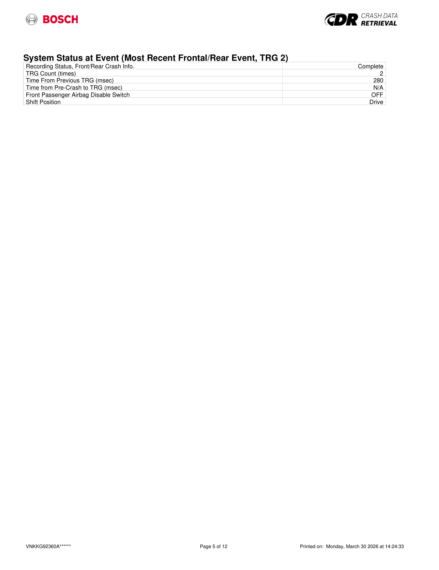
Read page 71 text
System Status at Event (Most Recent Frontal/Rear Event, TRG 2) Recording Status, Front/Rear Crash Info. Complete TRG Count (times) 2 Time From Previous TRG (msec) 280 Time from Pre-Crash to TRG (msec) N/A Front Passenger Airbag Disable Switch OFF Shift Position Drive VNKKG92360A****** Page 5 of 12 Printed on: Monday, March 30 2026 at 14:24:33
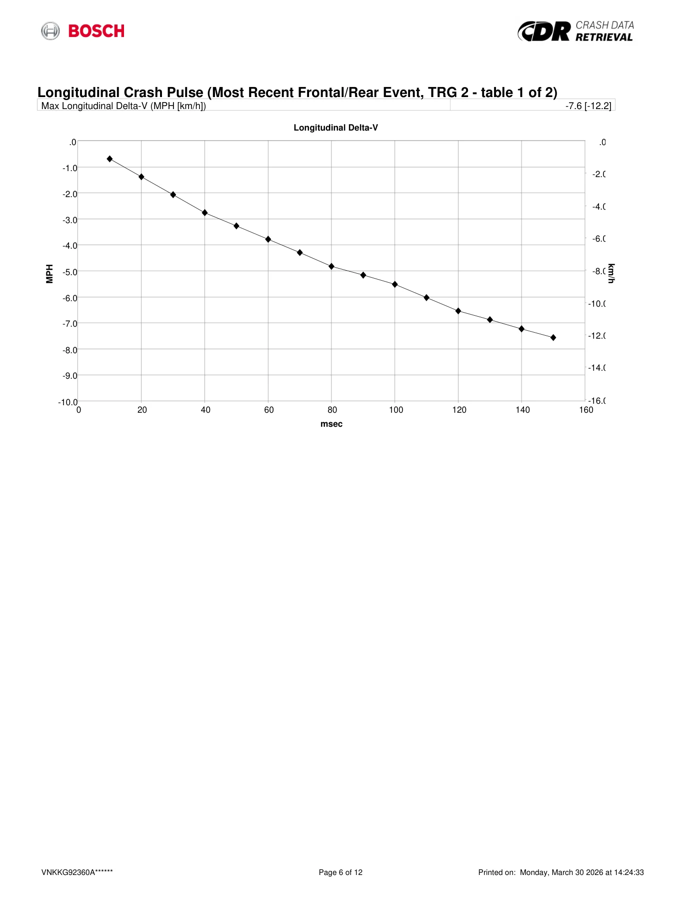
Read page 72 text
Longitudinal Crash Pulse (Most Recent Frontal/Rear Event, TRG 2 - table 1 of 2) Max Longitudinal Delta-V (MPH [km/h]) -7.6 [-12.2] -10.0 -9.0 -8.0 -7.0 -6.0 -5.0 -4.0 -3.0 -2.0 -1.0 .0 .0 -2.0 -4.0 -6.0 -8.0 -10.0 -12.0 -14.0 -16.0 0 20 40 60 80 100 120 140 160 MPH km/h Longitudinal Delta-V Longitudinal Delta-V msec VNKKG92360A****** Page 6 of 12 Printed on: Monday, March 30 2026 at 14:24:33
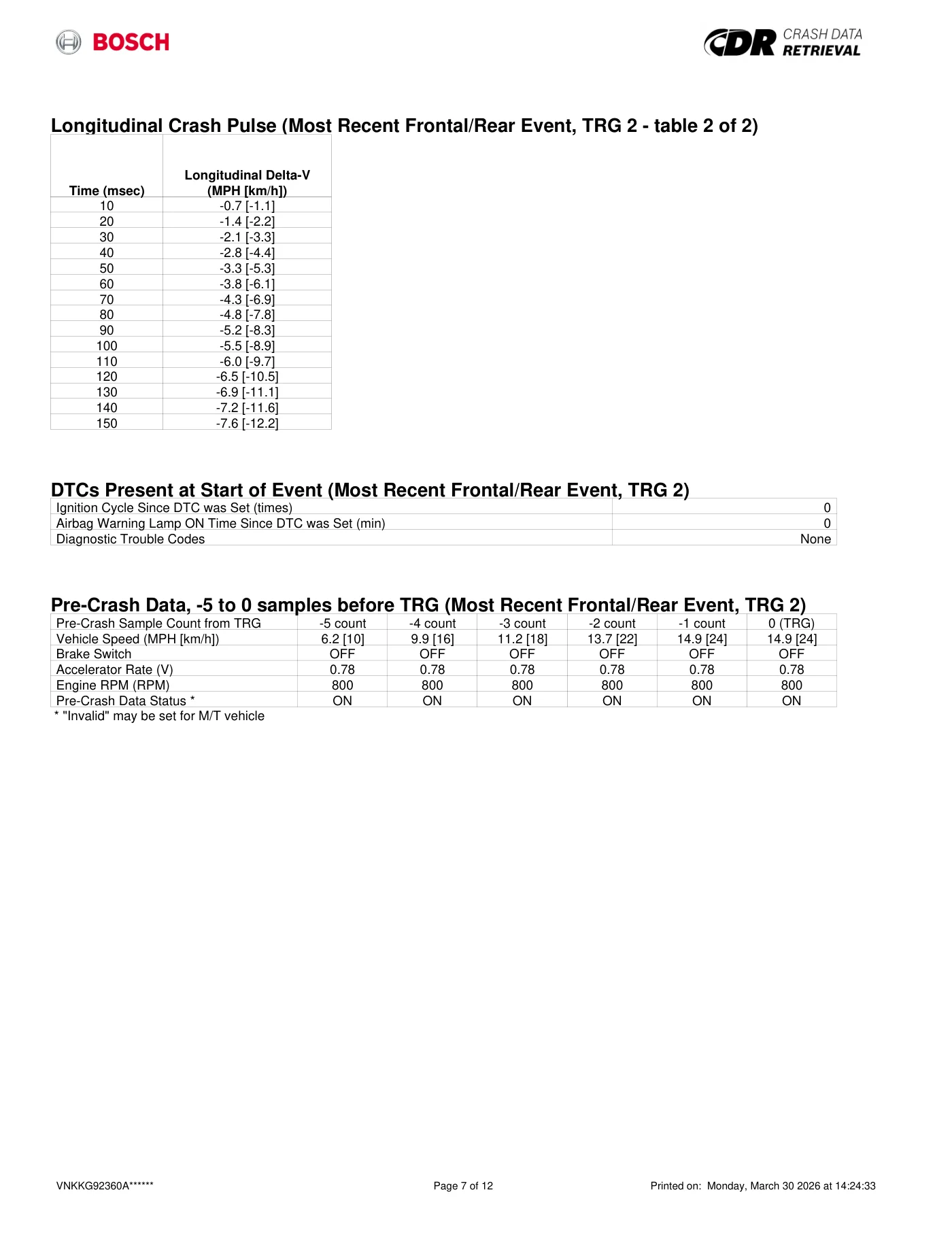
Read page 73 text
Longitudinal Crash Pulse (Most Recent Frontal/Rear Event, TRG 2 - table 2 of 2) Time (msec) Longitudinal Delta-V (MPH [km/h]) 10 -0.7 [-1.1] 20 -1.4 [-2.2] 30 -2.1 [-3.3] 40 -2.8 [-4.4] 50 -3.3 [-5.3] 60 -3.8 [-6.1] 70 -4.3 [-6.9] 80 -4.8 [-7.8] 90 -5.2 [-8.3] 100 -5.5 [-8.9] 110 -6.0 [-9.7] 120 -6.5 [-10.5] 130 -6.9 [-11.1] 140 -7.2 [-11.6] 150 -7.6 [-12.2] DTCs Present at Start of Event (Most Recent Frontal/Rear Event, TRG 2) Ignition Cycle Since DTC was Set (times) 0 Airbag Warning Lamp ON Time Since DTC was Set (min) 0 Diagnostic Trouble Codes None Pre-Crash Data, -5 to 0 samples before TRG (Most Recent Frontal/Rear Event, TRG 2) Pre-Crash Sample Count from TRG -5 count -4 count -3 count -2 count -1 count 0 (TRG) Vehicle Speed (MPH [km/h]) 6.2 [10] 9.9 [16] 11.2 [18] 13.7 [22] 14.9 [24] 14.9 [24] Brake Switch OFF OFF OFF OFF OFF OFF Accelerator Rate (V) 0.78 0.78 0.78 0.78 0.78 0.78 Engine RPM (RPM) 800 800 800 800 800 800 Pre-Crash Data Status * ON ON ON ON ON ON * "Invalid" may be set for M/T vehicle VNKKG92360A****** Page 7 of 12 Printed on: Monday, March 30 2026 at 14:24:33
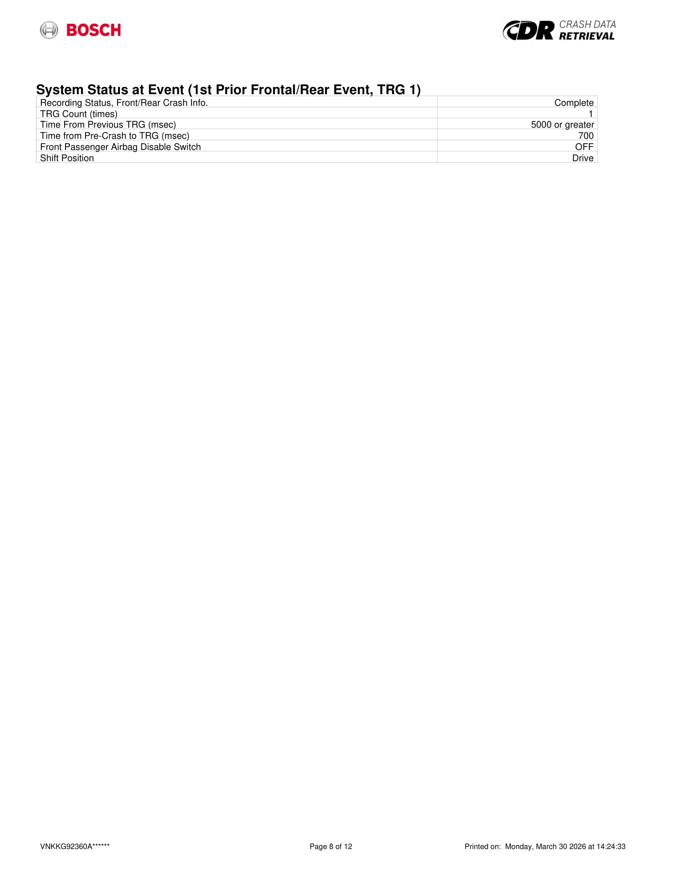
Read page 74 text
System Status at Event (1st Prior Frontal/Rear Event, TRG 1) Recording Status, Front/Rear Crash Info. Complete TRG Count (times) 1 Time From Previous TRG (msec) 5000 or greater Time from Pre-Crash to TRG (msec) 700 Front Passenger Airbag Disable Switch OFF Shift Position Drive VNKKG92360A****** Page 8 of 12 Printed on: Monday, March 30 2026 at 14:24:33
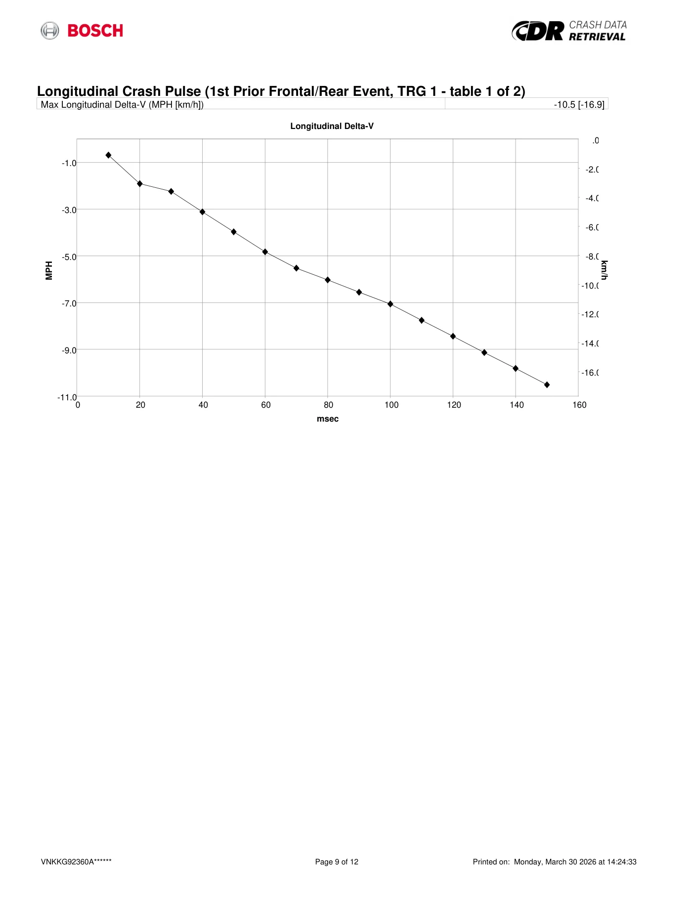
Read page 75 text
Longitudinal Crash Pulse (1st Prior Frontal/Rear Event, TRG 1 - table 1 of 2) Max Longitudinal Delta-V (MPH [km/h]) -10.5 [-16.9] -11.0 -9.0 -7.0 -5.0 -3.0 -1.0 .0 -2.0 -4.0 -6.0 -8.0 -10.0 -12.0 -14.0 -16.0 0 20 40 60 80 100 120 140 160 MPH km/h Longitudinal Delta-V Longitudinal Delta-V msec VNKKG92360A****** Page 9 of 12 Printed on: Monday, March 30 2026 at 14:24:33
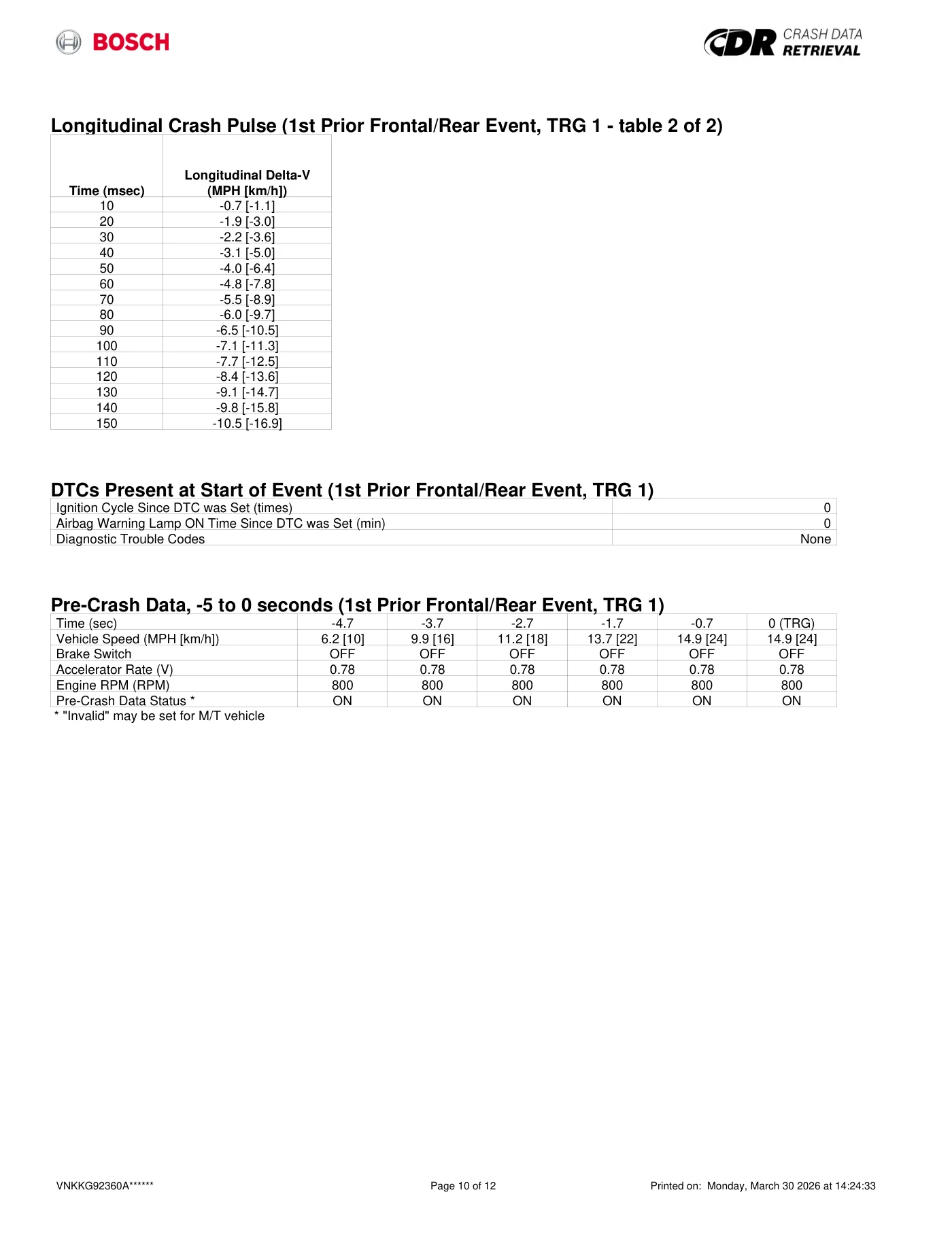
Read page 76 text
Longitudinal Crash Pulse (1st Prior Frontal/Rear Event, TRG 1 - table 2 of 2) Time (msec) Longitudinal Delta-V (MPH [km/h]) 10 -0.7 [-1.1] 20 -1.9 [-3.0] 30 -2.2 [-3.6] 40 -3.1 [-5.0] 50 -4.0 [-6.4] 60 -4.8 [-7.8] 70 -5.5 [-8.9] 80 -6.0 [-9.7] 90 -6.5 [-10.5] 100 -7.1 [-11.3] 110 -7.7 [-12.5] 120 -8.4 [-13.6] 130 -9.1 [-14.7] 140 -9.8 [-15.8] 150 -10.5 [-16.9] DTCs Present at Start of Event (1st Prior Frontal/Rear Event, TRG 1) Ignition Cycle Since DTC was Set (times) 0 Airbag Warning Lamp ON Time Since DTC was Set (min) 0 Diagnostic Trouble Codes None Pre-Crash Data, -5 to 0 seconds (1st Prior Frontal/Rear Event, TRG 1) Time (sec) -4.7 -3.7 -2.7 -1.7 -0.7 0 (TRG) Vehicle Speed (MPH [km/h]) 6.2 [10] 9.9 [16] 11.2 [18] 13.7 [22] 14.9 [24] 14.9 [24] Brake Switch OFF OFF OFF OFF OFF OFF Accelerator Rate (V) 0.78 0.78 0.78 0.78 0.78 0.78 Engine RPM (RPM) 800 800 800 800 800 800 Pre-Crash Data Status * ON ON ON ON ON ON * "Invalid" may be set for M/T vehicle VNKKG92360A****** Page 10 of 12 Printed on: Monday, March 30 2026 at 14:24:33
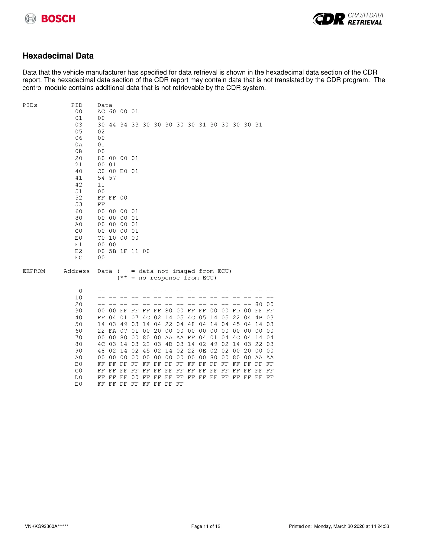
Read page 77 text
Hexadecimal Data Data that the vehicle manufacturer has specified for data retrieval is shown in the hexadecimal data section of the CDR report. The hexadecimal data section of the CDR report may contain data that is not translated by the CDR program. The control module contains additional data that is not retrievable by the CDR system. PIDs PID Data 00 AC 60 00 01 01 00 03 30 44 34 33 30 30 30 30 30 31 30 30 30 30 31 05 02 06 00 0A 01 0B 00 20 80 00 00 01 21 00 01 40 C0 00 E0 01 41 54 57 42 11 51 00 52 FF FF 00 53 FF 60 00 00 00 01 80 00 00 00 01 A0 00 00 00 01 C0 00 00 00 01 E0 C0 10 00 00 E1 00 00 E2 00 5B 1F 11 00 EC 00 EEPROM Address Data (-- = data not imaged from ECU) (** = no response from ECU) 0 -- -- -- -- -- -- -- -- -- -- -- -- -- -- -- -- 10 -- -- -- -- -- -- -- -- -- -- -- -- -- -- -- -- 20 -- -- -- -- -- -- -- -- -- -- -- -- -- -- 80 00 30 00 00 FF FF FF FF 80 00 FF FF 00 00 FD 00 FF FF 40 FF 04 01 07 4C 02 14 05 4C 05 14 05 22 04 4B 03 50 14 03 49 03 14 04 22 04 48 04 14 04 45 04 14 03 60 22 FA 07 01 00 20 00 00 00 00 00 00 00 00 00 00 70 00 00 80 00 80 00 AA AA FF 04 01 04 4C 04 14 04 80 4C 03 14 03 22 03 4B 03 14 02 49 02 14 03 22 03 90 48 02 14 02 45 02 14 02 22 0E 02 02 00 20 00 00 A0 00 00 00 00 00 00 00 00 00 00 80 00 80 00 AA AA B0 FF FF FF FF FF FF FF FF FF FF FF FF FF FF FF FF C0 FF FF FF FF FF FF FF FF FF FF FF FF FF FF FF FF D0 FF FF FF 00 FF FF FF FF FF FF FF FF FF FF FF FF E0 FF FF FF FF FF FF FF FF VNKKG92360A****** Page 11 of 12 Printed on: Monday, March 30 2026 at 14:24:33

Read page 78 text
Disclaimer of Liability The users of the CDR product and reviewers of the CDR reports and exported data shall ensure that data and information supplied is applicable to the vehicle, vehicle's system(s) and the vehicle ECU. Robert Bosch LLC and all its directors, officers, employees and members shall not be liable for damages arising out of or related to incorrect, incomplete or misinterpreted software and/or data. Robert Bosch LLC expressly excludes all liability for incidental, consequential, special or punitive damages arising from or related to the CDR data, CDR software or use thereof. VNKKG92360A****** Page 12 of 12 Printed on: Monday, March 30 2026 at 14:24:33

Read page 79 text
EDR Europe SL - C.I.F: B02716520 Tfno: 828 027 557 • E-mail: info@edr-europe.eu ANEXO 3: Tablas comparativas
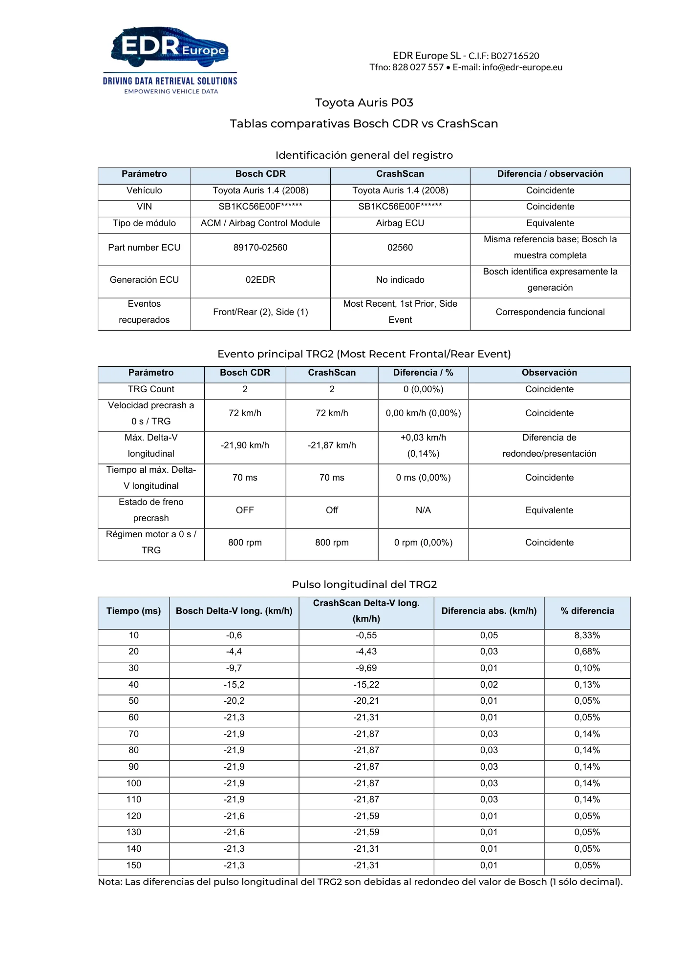
Read page 80 text
EDR Europe SL - C.I.F: B02716520 Tfno: 828 027 557 • E-mail: info@edr-europe.eu Toyota Auris P03 Tablas comparativas Bosch CDR vs CrashScan Identificación general del registro Parámetro Bosch CDR CrashScan Diferencia / observación Vehículo Toyota Auris 1.4 (2008) Toyota Auris 1.4 (2008) Coincidente VIN SB1KC56E00F****** SB1KC56E00F****** Coincidente Tipo de módulo ACM / Airbag Control Module Airbag ECU Equivalente Part number ECU 89170-02560 02560 Misma referencia base; Bosch la muestra completa Generación ECU 02EDR No indicado Bosch identifica expresamente la generación Eventos recuperados Front/Rear (2), Side (1) Most Recent, 1st Prior, Side Event Correspondencia funcional Evento principal TRG2 (Most Recent Frontal/Rear Event) Parámetro Bosch CDR CrashScan Diferencia / % Observación TRG Count 2 2 0 (0,00%) Coincidente Velocidad precrash a 0 s / TRG 72 km/h 72 km/h 0,00 km/h (0,00%) Coincidente Máx. Delta-V longitudinal -21,90 km/h -21,87 km/h +0,03 km/h (0,14%) Diferencia de redondeo/presentación Tiempo al máx. Delta- V longitudinal 70 ms 70 ms 0 ms (0,00%) Coincidente Estado de freno precrash OFF Off N/A Equivalente Régimen motor a 0 s / TRG 800 rpm 800 rpm 0 rpm (0,00%) Coincidente Pulso longitudinal del TRG2 Tiempo (ms) Bosch Delta-V long. (km/h) CrashScan Delta-V long. (km/h) Diferencia abs. (km/h) % diferencia 10 -0,6 -0,55 0,05 8,33% 20 -4,4 -4,43 0,03 0,68% 30 -9,7 -9,69 0,01 0,10% 40 -15,2 -15,22 0,02 0,13% 50 -20,2 -20,21 0,01 0,05% 60 -21,3 -21,31 0,01 0,05% 70 -21,9 -21,87 0,03 0,14% 80 -21,9 -21,87 0,03 0,14% 90 -21,9 -21,87 0,03 0,14% 100 -21,9 -21,87 0,03 0,14% 110 -21,9 -21,87 0,03 0,14% 120 -21,6 -21,59 0,01 0,05% 130 -21,6 -21,59 0,01 0,05% 140 -21,3 -21,31 0,01 0,05% 150 -21,3 -21,31 0,01 0,05% Nota: Las diferencias del pulso longitudinal del TRG2 son debidas al redondeo del valor de Bosch (1 sólo decimal).
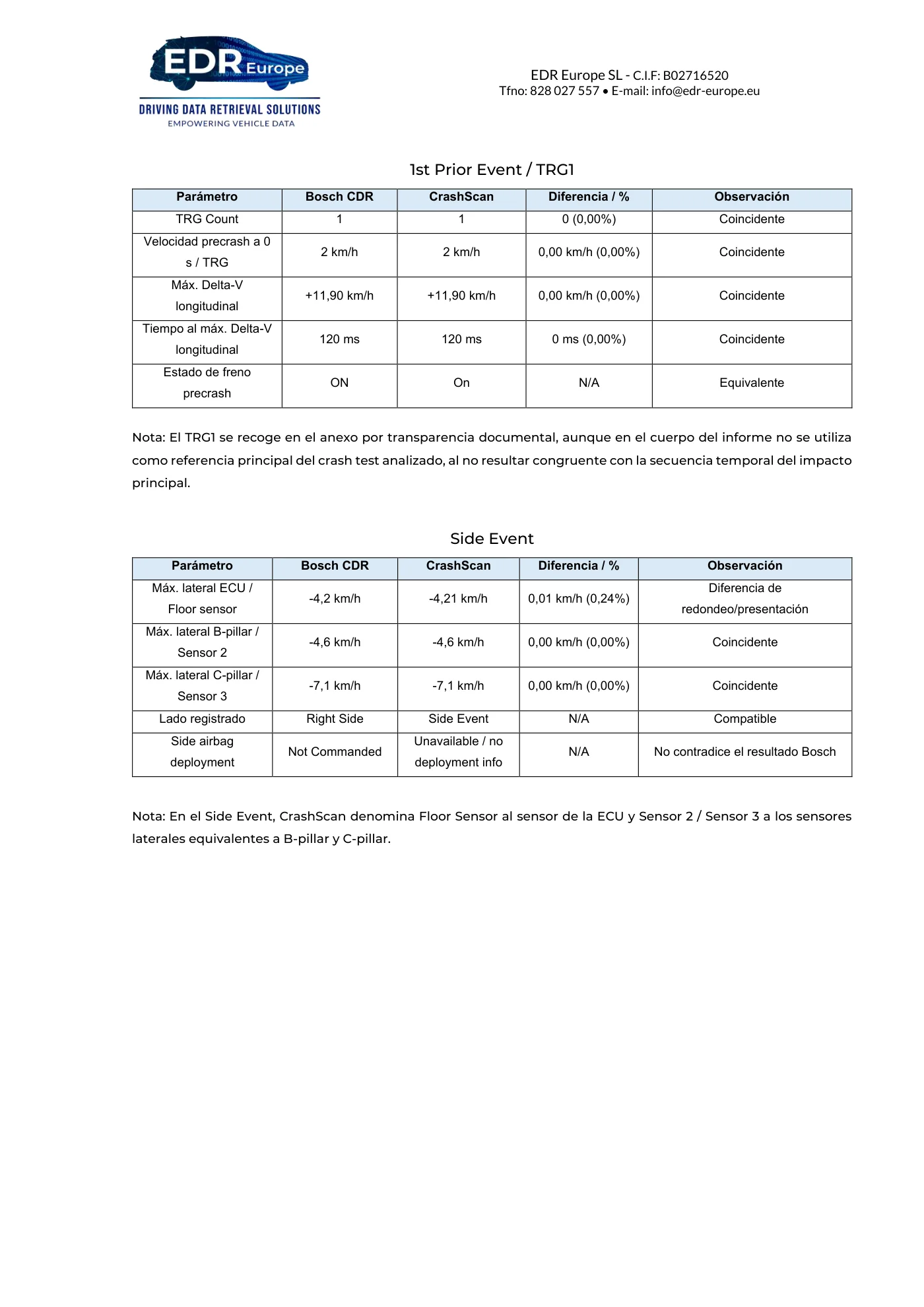
Read page 81 text
EDR Europe SL - C.I.F: B02716520 Tfno: 828 027 557 • E-mail: info@edr-europe.eu 1st Prior Event / TRG1 Parámetro Bosch CDR CrashScan Diferencia / % Observación TRG Count 1 1 0 (0,00%) Coincidente Velocidad precrash a 0 s / TRG 2 km/h 2 km/h 0,00 km/h (0,00%) Coincidente Máx. Delta-V longitudinal +11,90 km/h +11,90 km/h 0,00 km/h (0,00%) Coincidente Tiempo al máx. Delta-V longitudinal 120 ms 120 ms 0 ms (0,00%) Coincidente Estado de freno precrash ON On N/A Equivalente Nota: El TRG1 se recoge en el anexo por transparencia documental, aunque en el cuerpo del informe no se utiliza como referencia principal del crash test analizado, al no resultar congruente con la secuencia temporal del impacto principal. Side Event Parámetro Bosch CDR CrashScan Diferencia / % Observación Máx. lateral ECU / Floor sensor -4,2 km/h -4,21 km/h 0,01 km/h (0,24%) Diferencia de redondeo/presentación Máx. lateral B-pillar / Sensor 2 -4,6 km/h -4,6 km/h 0,00 km/h (0,00%) Coincidente Máx. lateral C-pillar / Sensor 3 -7,1 km/h -7,1 km/h 0,00 km/h (0,00%) Coincidente Lado registrado Right Side Side Event N/A Compatible Side airbag deployment Not Commanded Unavailable / no deployment info N/A No contradice el resultado Bosch Nota: En el Side Event, CrashScan denomina Floor Sensor al sensor de la ECU y Sensor 2 / Sensor 3 a los sensores laterales equivalentes a B-pillar y C-pillar.
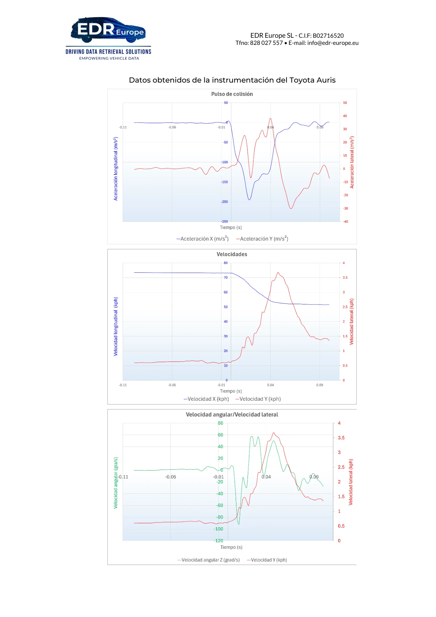
Read page 82 text
EDR Europe SL - C.I.F: B02716520 Tfno: 828 027 557 • E-mail: info@edr-europe.eu Datos obtenidos de la instrumentación del Toyota Auris
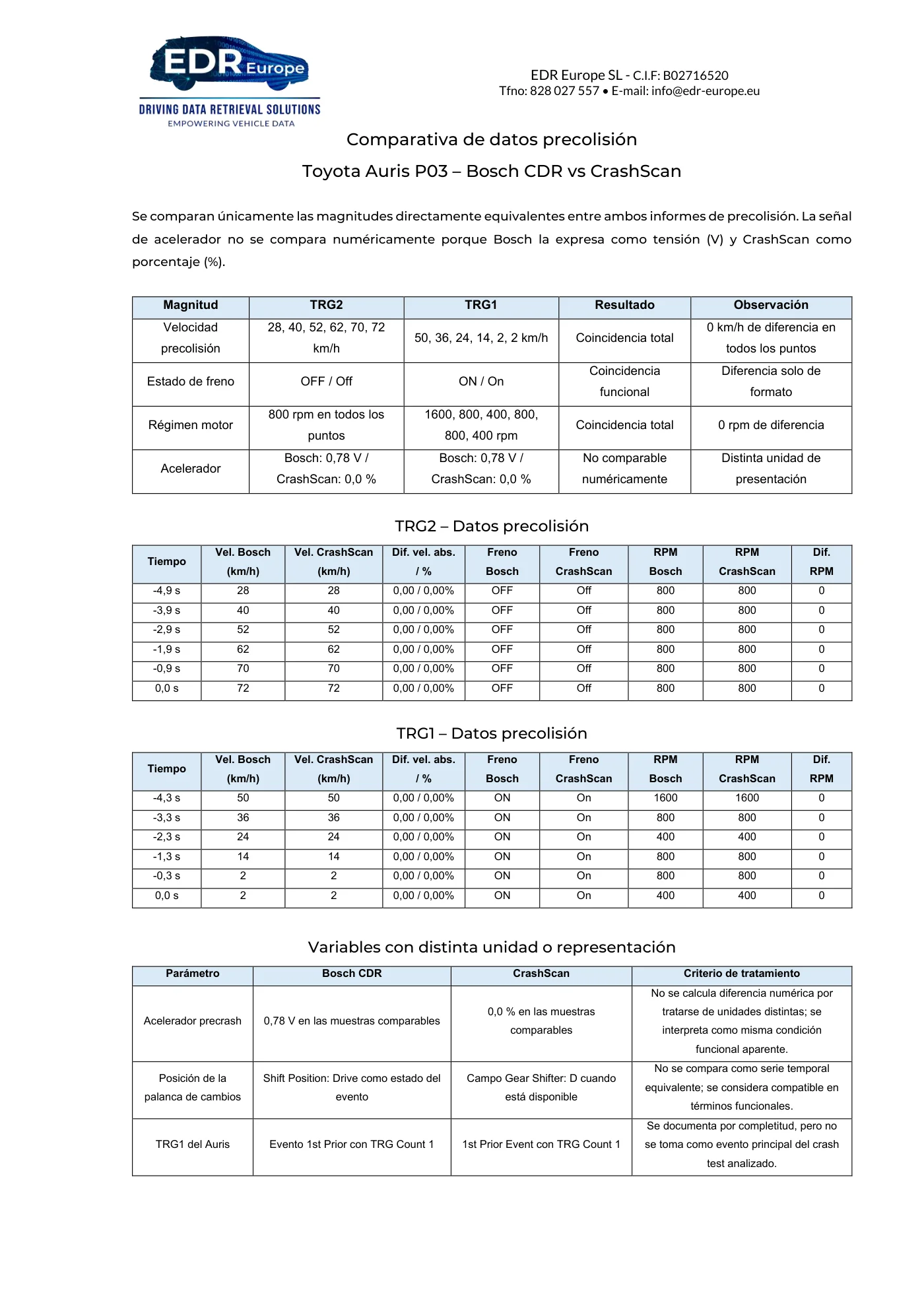
Read page 83 text
EDR Europe SL - C.I.F: B02716520 Tfno: 828 027 557 • E-mail: info@edr-europe.eu Comparativa de datos precolisión Toyota Auris P03 – Bosch CDR vs CrashScan Se comparan únicamente las magnitudes directamente equivalentes entre ambos informes de precolisión. La señal de acelerador no se compara numéricamente porque Bosch la expresa como tensión (V) y CrashScan como porcentaje (%). Magnitud TRG2 TRG1 Resultado Observación Velocidad precolisión 28, 40, 52, 62, 70, 72 km/h 50, 36, 24, 14, 2, 2 km/h Coincidencia total 0 km/h de diferencia en todos los puntos Estado de freno OFF / Off ON / On Coincidencia funcional Diferencia solo de formato Régimen motor 800 rpm en todos los puntos 1600, 800, 400, 800, 800, 400 rpm Coincidencia total 0 rpm de diferencia Acelerador Bosch: 0,78 V / CrashScan: 0,0 % Bosch: 0,78 V / CrashScan: 0,0 % No comparable numéricamente Distinta unidad de presentación TRG2 – Datos precolisión Tiempo Vel. Bosch (km/h) Vel. CrashScan (km/h) Dif. vel. abs. / % Freno Bosch Freno CrashScan RPM Bosch RPM CrashScan Dif. RPM -4,9 s 28 28 0,00 / 0,00% OFF Off 800 800 0 -3,9 s 40 40 0,00 / 0,00% OFF Off 800 800 0 -2,9 s 52 52 0,00 / 0,00% OFF Off 800 800 0 -1,9 s 62 62 0,00 / 0,00% OFF Off 800 800 0 -0,9 s 70 70 0,00 / 0,00% OFF Off 800 800 0 0,0 s 72 72 0,00 / 0,00% OFF Off 800 800 0 TRG1 – Datos precolisión Tiempo Vel. Bosch (km/h) Vel. CrashScan (km/h) Dif. vel. abs. / % Freno Bosch Freno CrashScan RPM Bosch RPM CrashScan Dif. RPM -4,3 s 50 50 0,00 / 0,00% ON On 1600 1600 0 -3,3 s 36 36 0,00 / 0,00% ON On 800 800 0 -2,3 s 24 24 0,00 / 0,00% ON On 400 400 0 -1,3 s 14 14 0,00 / 0,00% ON On 800 800 0 -0,3 s 2 2 0,00 / 0,00% ON On 800 800 0 0,0 s 2 2 0,00 / 0,00% ON On 400 400 0 Variables con distinta unidad o representación Parámetro Bosch CDR CrashScan Criterio de tratamiento Acelerador precrash 0,78 V en las muestras comparables 0,0 % en las muestras comparables No se calcula diferencia numérica por tratarse de unidades distintas; se interpreta como misma condición funcional aparente. Posición de la palanca de cambios Shift Position: Drive como estado del evento Campo Gear Shifter: D cuando está disponible No se compara como serie temporal equivalente; se considera compatible en términos funcionales. TRG1 del Auris Evento 1st Prior con TRG Count 1 1st Prior Event con TRG Count 1 Se documenta por completitud, pero no se toma como evento principal del crash test analizado.
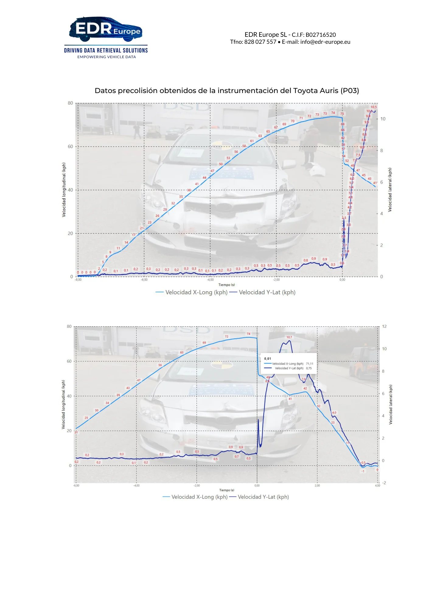
Read page 84 text
EDR Europe SL - C.I.F: B02716520 Tfno: 828 027 557 • E-mail: info@edr-europe.eu Datos precolisión obtenidos de la instrumentación del Toyota Auris (P03)
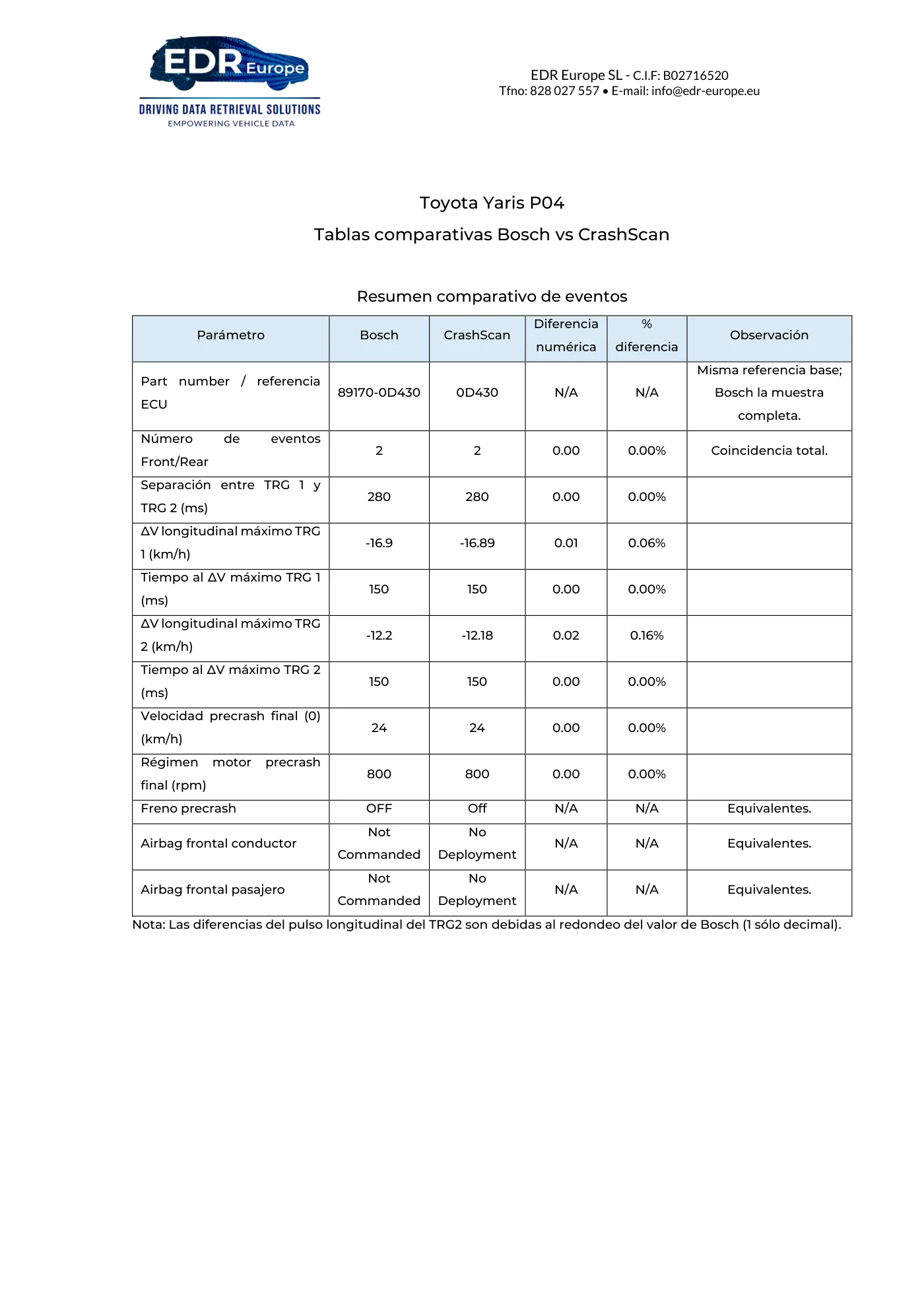
Read page 85 text
EDR Europe SL - C.I.F: B02716520 Tfno: 828 027 557 • E-mail: info@edr-europe.eu Toyota Yaris P04 Tablas comparativas Bosch vs CrashScan Resumen comparativo de eventos Parámetro Bosch CrashScan Diferencia numérica % diferencia Observación Part number / referencia ECU 89170-0D430 0D430 N/A N/A Misma referencia base; Bosch la muestra completa. Número de eventos Front/Rear 2 2 0.00 0.00% Coincidencia total. Separación entre TRG 1 y TRG 2 (ms) 280 280 0.00 0.00% ΔV longitudinal máximo TRG 1 (km/h) -16.9 -16.89 0.01 0.06% Tiempo al ΔV máximo TRG 1 (ms) 150 150 0.00 0.00% ΔV longitudinal máximo TRG 2 (km/h) -12.2 -12.18 0.02 0.16% Tiempo al ΔV máximo TRG 2 (ms) 150 150 0.00 0.00% Velocidad precrash final (0) (km/h) 24 24 0.00 0.00% Régimen motor precrash final (rpm) 800 800 0.00 0.00% Freno precrash OFF Off N/A N/A Equivalentes. Airbag frontal conductor Not Commanded No Deployment N/A N/A Equivalentes. Airbag frontal pasajero Not Commanded No Deployment N/A N/A Equivalentes. Nota: Las diferencias del pulso longitudinal del TRG2 son debidas al redondeo del valor de Bosch (1 sólo decimal).
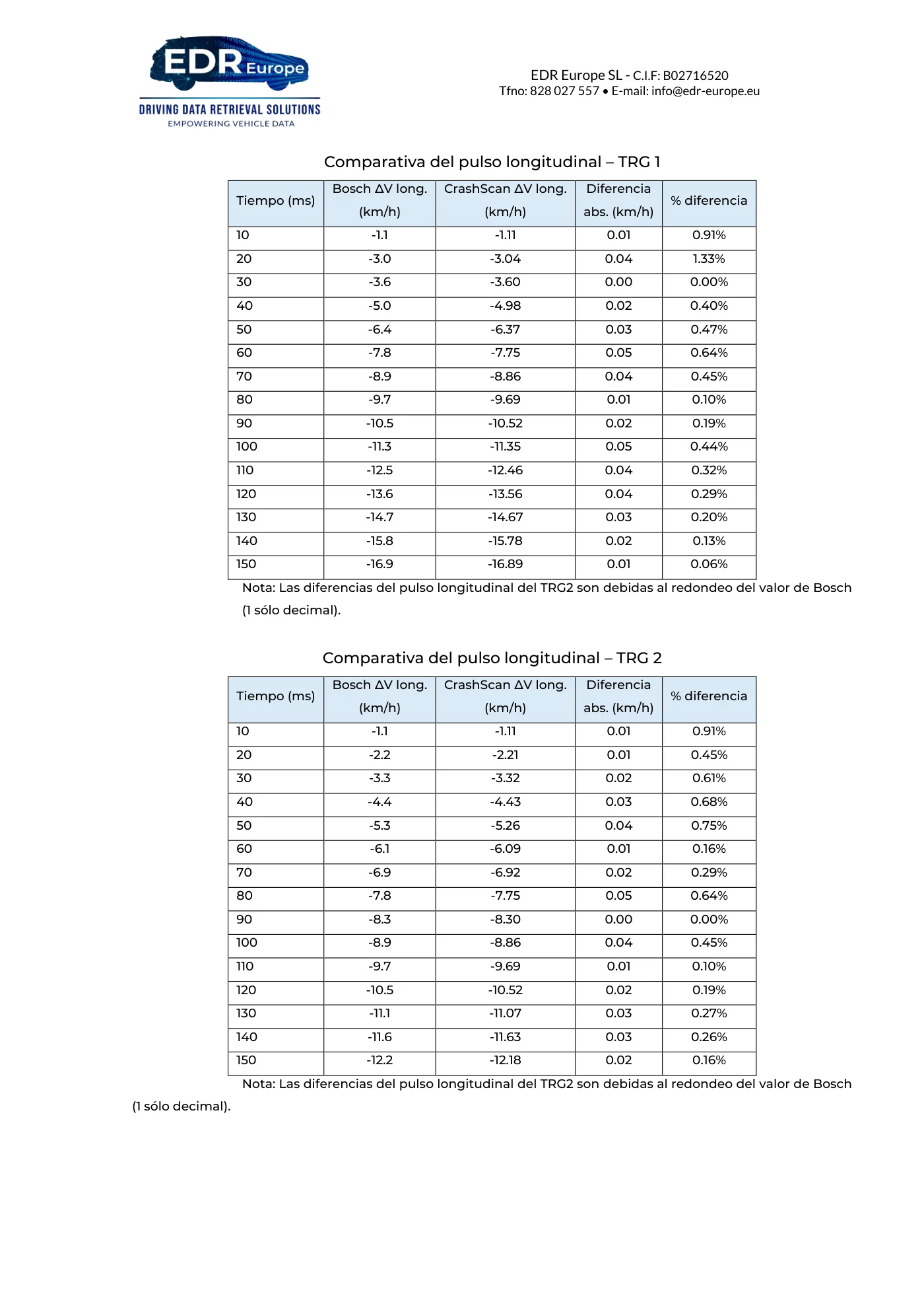
Read page 86 text
EDR Europe SL - C.I.F: B02716520 Tfno: 828 027 557 • E-mail: info@edr-europe.eu Comparativa del pulso longitudinal – TRG 1 Tiempo (ms) Bosch ΔV long. (km/h) CrashScan ΔV long. (km/h) Diferencia abs. (km/h) % diferencia 10 -1.1 -1.11 0.01 0.91% 20 -3.0 -3.04 0.04 1.33% 30 -3.6 -3.60 0.00 0.00% 40 -5.0 -4.98 0.02 0.40% 50 -6.4 -6.37 0.03 0.47% 60 -7.8 -7.75 0.05 0.64% 70 -8.9 -8.86 0.04 0.45% 80 -9.7 -9.69 0.01 0.10% 90 -10.5 -10.52 0.02 0.19% 100 -11.3 -11.35 0.05 0.44% 110 -12.5 -12.46 0.04 0.32% 120 -13.6 -13.56 0.04 0.29% 130 -14.7 -14.67 0.03 0.20% 140 -15.8 -15.78 0.02 0.13% 150 -16.9 -16.89 0.01 0.06% Nota: Las diferencias del pulso longitudinal del TRG2 son debidas al redondeo del valor de Bosch (1 sólo decimal). Comparativa del pulso longitudinal – TRG 2 Tiempo (ms) Bosch ΔV long. (km/h) CrashScan ΔV long. (km/h) Diferencia abs. (km/h) % diferencia 10 -1.1 -1.11 0.01 0.91% 20 -2.2 -2.21 0.01 0.45% 30 -3.3 -3.32 0.02 0.61% 40 -4.4 -4.43 0.03 0.68% 50 -5.3 -5.26 0.04 0.75% 60 -6.1 -6.09 0.01 0.16% 70 -6.9 -6.92 0.02 0.29% 80 -7.8 -7.75 0.05 0.64% 90 -8.3 -8.30 0.00 0.00% 100 -8.9 -8.86 0.04 0.45% 110 -9.7 -9.69 0.01 0.10% 120 -10.5 -10.52 0.02 0.19% 130 -11.1 -11.07 0.03 0.27% 140 -11.6 -11.63 0.03 0.26% 150 -12.2 -12.18 0.02 0.16% Nota: Las diferencias del pulso longitudinal del TRG2 son debidas al redondeo del valor de Bosch (1 sólo decimal).
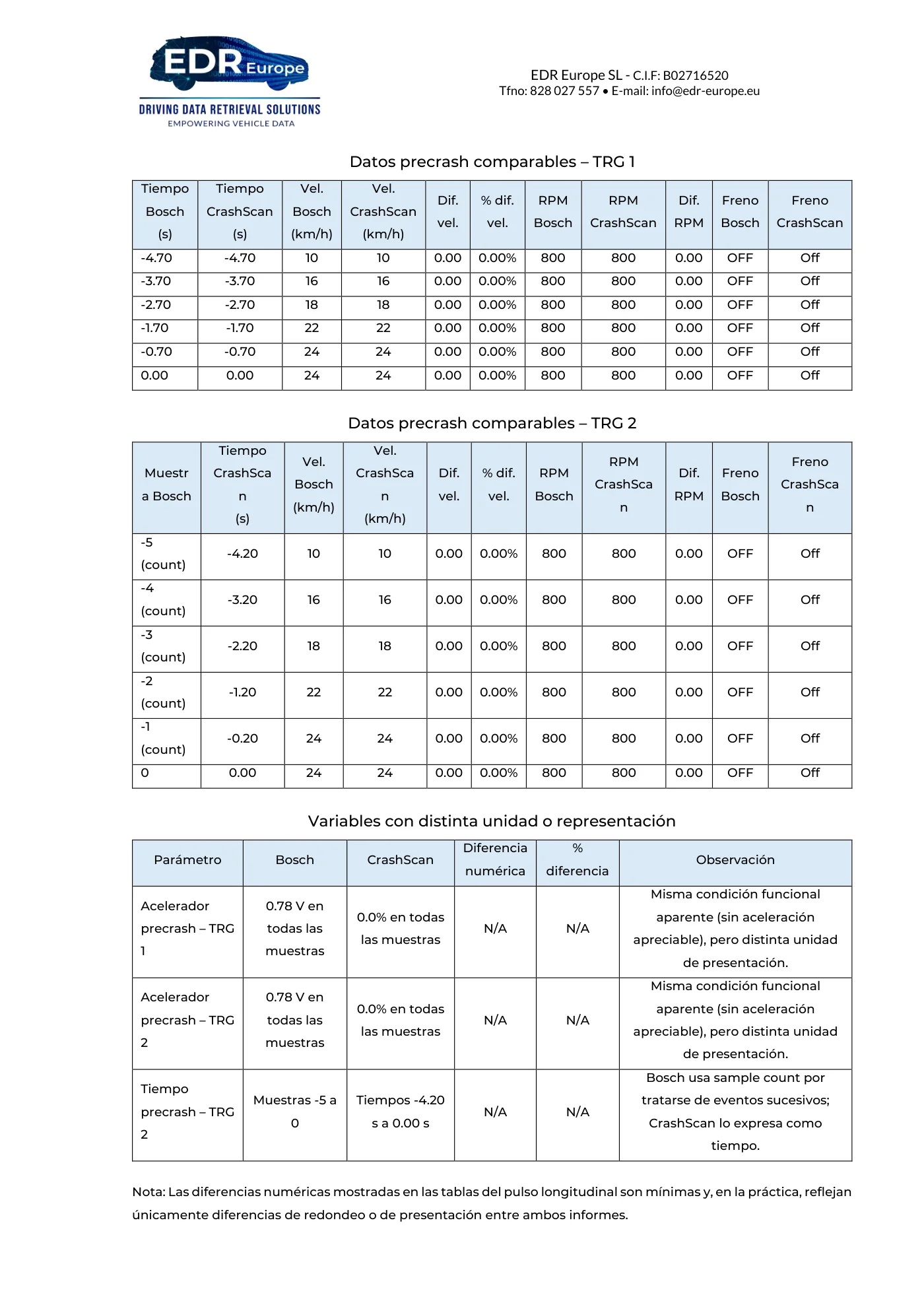
Read page 87 text
EDR Europe SL - C.I.F: B02716520 Tfno: 828 027 557 • E-mail: info@edr-europe.eu Datos precrash comparables – TRG 1 Tiempo Bosch (s) Tiempo CrashScan (s) Vel. Bosch (km/h) Vel. CrashScan (km/h) Dif. vel. % dif. vel. RPM Bosch RPM CrashScan Dif. RPM Freno Bosch Freno CrashScan -4.70 -4.70 10 10 0.00 0.00% 800 800 0.00 OFF Off -3.70 -3.70 16 16 0.00 0.00% 800 800 0.00 OFF Off -2.70 -2.70 18 18 0.00 0.00% 800 800 0.00 OFF Off -1.70 -1.70 22 22 0.00 0.00% 800 800 0.00 OFF Off -0.70 -0.70 24 24 0.00 0.00% 800 800 0.00 OFF Off 0.00 0.00 24 24 0.00 0.00% 800 800 0.00 OFF Off Datos precrash comparables – TRG 2 Muestr a Bosch Tiempo CrashSca n (s) Vel. Bosch (km/h) Vel. CrashSca n (km/h) Dif. vel. % dif. vel. RPM Bosch RPM CrashSca n Dif. RPM Freno Bosch Freno CrashSca n -5 (count) -4.20 10 10 0.00 0.00% 800 800 0.00 OFF Off -4 (count) -3.20 16 16 0.00 0.00% 800 800 0.00 OFF Off -3 (count) -2.20 18 18 0.00 0.00% 800 800 0.00 OFF Off -2 (count) -1.20 22 22 0.00 0.00% 800 800 0.00 OFF Off -1 (count) -0.20 24 24 0.00 0.00% 800 800 0.00 OFF Off 0 0.00 24 24 0.00 0.00% 800 800 0.00 OFF Off Variables con distinta unidad o representación Parámetro Bosch CrashScan Diferencia numérica % diferencia Observación Acelerador precrash – TRG 1 0.78 V en todas las muestras 0.0% en todas las muestras N/A N/A Misma condición funcional aparente (sin aceleración apreciable), pero distinta unidad de presentación. Acelerador precrash – TRG 2 0.78 V en todas las muestras 0.0% en todas las muestras N/A N/A Misma condición funcional aparente (sin aceleración apreciable), pero distinta unidad de presentación. Tiempo precrash – TRG 2 Muestras -5 a 0 Tiempos -4.20 s a 0.00 s N/A N/A Bosch usa sample count por tratarse de eventos sucesivos; CrashScan lo expresa como tiempo. Nota: Las diferencias numéricas mostradas en las tablas del pulso longitudinal son mínimas y, en la práctica, reflejan únicamente diferencias de redondeo o de presentación entre ambos informes.
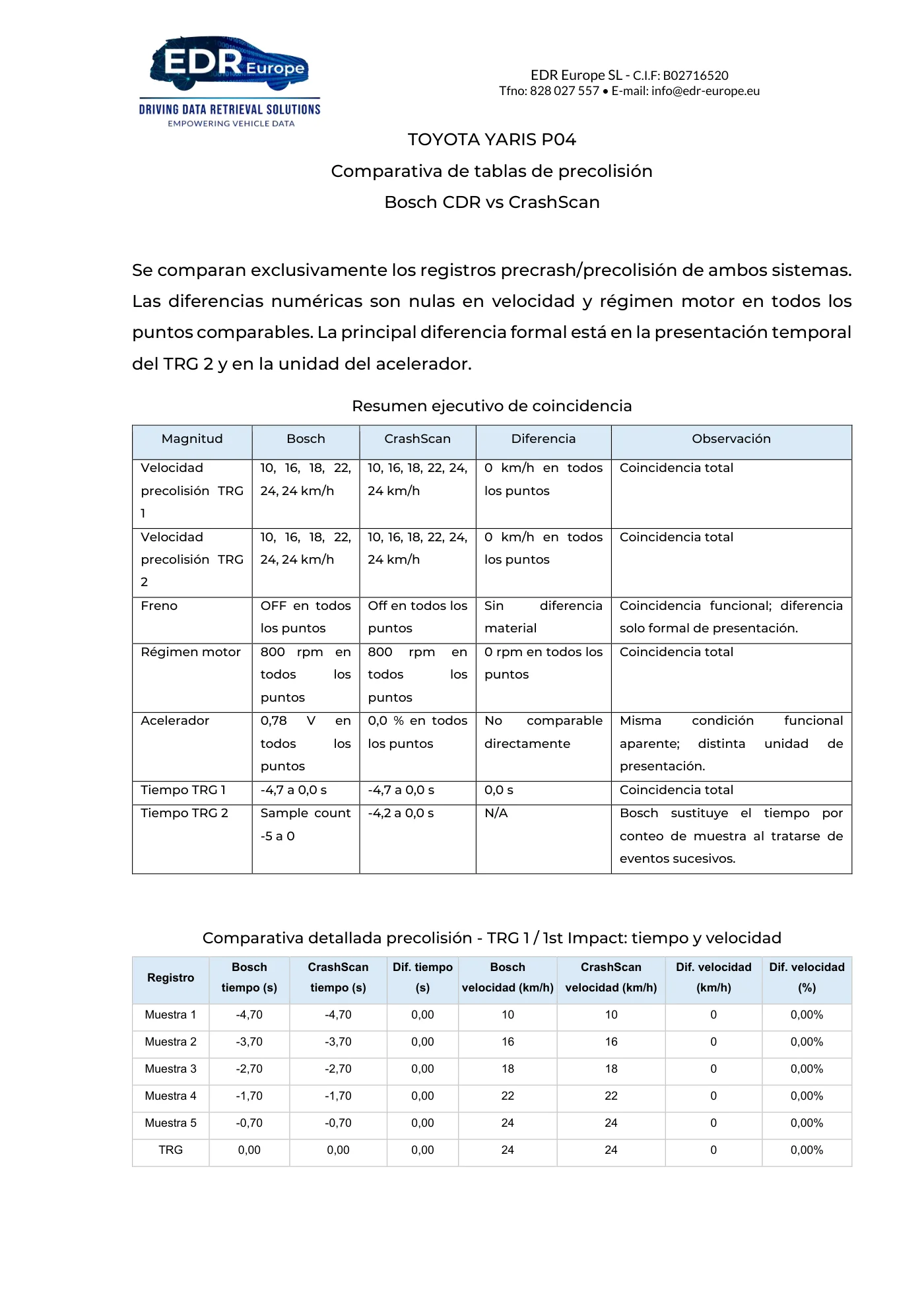
Read page 88 text
EDR Europe SL - C.I.F: B02716520 Tfno: 828 027 557 • E-mail: info@edr-europe.eu TOYOTA YARIS P04 Comparativa de tablas de precolisión Bosch CDR vs CrashScan Se comparan exclusivamente los registros precrash/precolisión de ambos sistemas. Las diferencias numéricas son nulas en velocidad y régimen motor en todos los puntos comparables. La principal diferencia formal está en la presentación temporal del TRG 2 y en la unidad del acelerador. Resumen ejecutivo de coincidencia Magnitud Bosch CrashScan Diferencia Observación Velocidad precolisión TRG 1 10, 16, 18, 22, 24, 24 km/h 10, 16, 18, 22, 24, 24 km/h 0 km/h en todos los puntos Coincidencia total Velocidad precolisión TRG 2 10, 16, 18, 22, 24, 24 km/h 10, 16, 18, 22, 24, 24 km/h 0 km/h en todos los puntos Coincidencia total Freno OFF en todos los puntos Off en todos los puntos Sin diferencia material Coincidencia funcional; diferencia solo formal de presentación. Régimen motor 800 rpm en todos los puntos 800 rpm en todos los puntos 0 rpm en todos los puntos Coincidencia total Acelerador 0,78 V en todos los puntos 0,0 % en todos los puntos No comparable directamente Misma condición funcional aparente; distinta unidad de presentación. Tiempo TRG 1 -4,7 a 0,0 s -4,7 a 0,0 s 0,0 s Coincidencia total Tiempo TRG 2 Sample count -5 a 0 -4,2 a 0,0 s N/A Bosch sustituye el tiempo por conteo de muestra al tratarse de eventos sucesivos. Comparativa detallada precolisión - TRG 1 / 1st Impact: tiempo y velocidad Registro Bosch tiempo (s) CrashScan tiempo (s) Dif. tiempo (s) Bosch velocidad (km/h) CrashScan velocidad (km/h) Dif. velocidad (km/h) Dif. velocidad (%) Muestra 1 -4,70 -4,70 0,00 10 10 0 0,00% Muestra 2 -3,70 -3,70 0,00 16 16 0 0,00% Muestra 3 -2,70 -2,70 0,00 18 18 0 0,00% Muestra 4 -1,70 -1,70 0,00 22 22 0 0,00% Muestra 5 -0,70 -0,70 0,00 24 24 0 0,00% TRG 0,00 0,00 0,00 24 24 0 0,00%
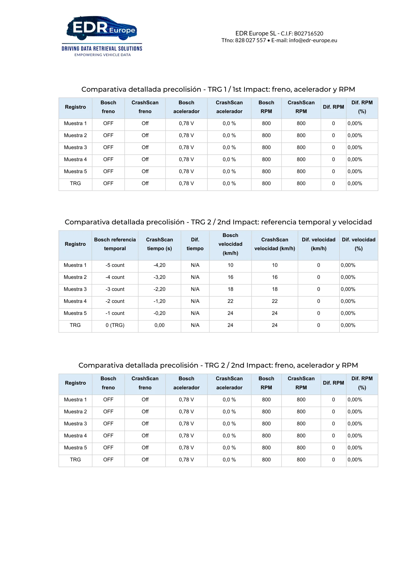
Read page 89 text
EDR Europe SL - C.I.F: B02716520 Tfno: 828 027 557 • E-mail: info@edr-europe.eu Comparativa detallada precolisión - TRG 1 / 1st Impact: freno, acelerador y RPM Registro Bosch freno CrashScan freno Bosch acelerador CrashScan acelerador Bosch RPM CrashScan RPM Dif. RPM Dif. RPM (%) Muestra 1 OFF Off 0,78 V 0,0 % 800 800 0 0,00% Muestra 2 OFF Off 0,78 V 0,0 % 800 800 0 0,00% Muestra 3 OFF Off 0,78 V 0,0 % 800 800 0 0,00% Muestra 4 OFF Off 0,78 V 0,0 % 800 800 0 0,00% Muestra 5 OFF Off 0,78 V 0,0 % 800 800 0 0,00% TRG OFF Off 0,78 V 0,0 % 800 800 0 0,00% Comparativa detallada precolisión - TRG 2 / 2nd Impact: referencia temporal y velocidad Registro Bosch referencia temporal CrashScan tiempo (s) Dif. tiempo Bosch velocidad (km/h) CrashScan velocidad (km/h) Dif. velocidad (km/h) Dif. velocidad (%) Muestra 1 -5 count -4,20 N/A 10 10 0 0,00% Muestra 2 -4 count -3,20 N/A 16 16 0 0,00% Muestra 3 -3 count -2,20 N/A 18 18 0 0,00% Muestra 4 -2 count -1,20 N/A 22 22 0 0,00% Muestra 5 -1 count -0,20 N/A 24 24 0 0,00% TRG 0 (TRG) 0,00 N/A 24 24 0 0,00% Comparativa detallada precolisión - TRG 2 / 2nd Impact: freno, acelerador y RPM Registro Bosch freno CrashScan freno Bosch acelerador CrashScan acelerador Bosch RPM CrashScan RPM Dif. RPM Dif. RPM (%) Muestra 1 OFF Off 0,78 V 0,0 % 800 800 0 0,00% Muestra 2 OFF Off 0,78 V 0,0 % 800 800 0 0,00% Muestra 3 OFF Off 0,78 V 0,0 % 800 800 0 0,00% Muestra 4 OFF Off 0,78 V 0,0 % 800 800 0 0,00% Muestra 5 OFF Off 0,78 V 0,0 % 800 800 0 0,00% TRG OFF Off 0,78 V 0,0 % 800 800 0 0,00%
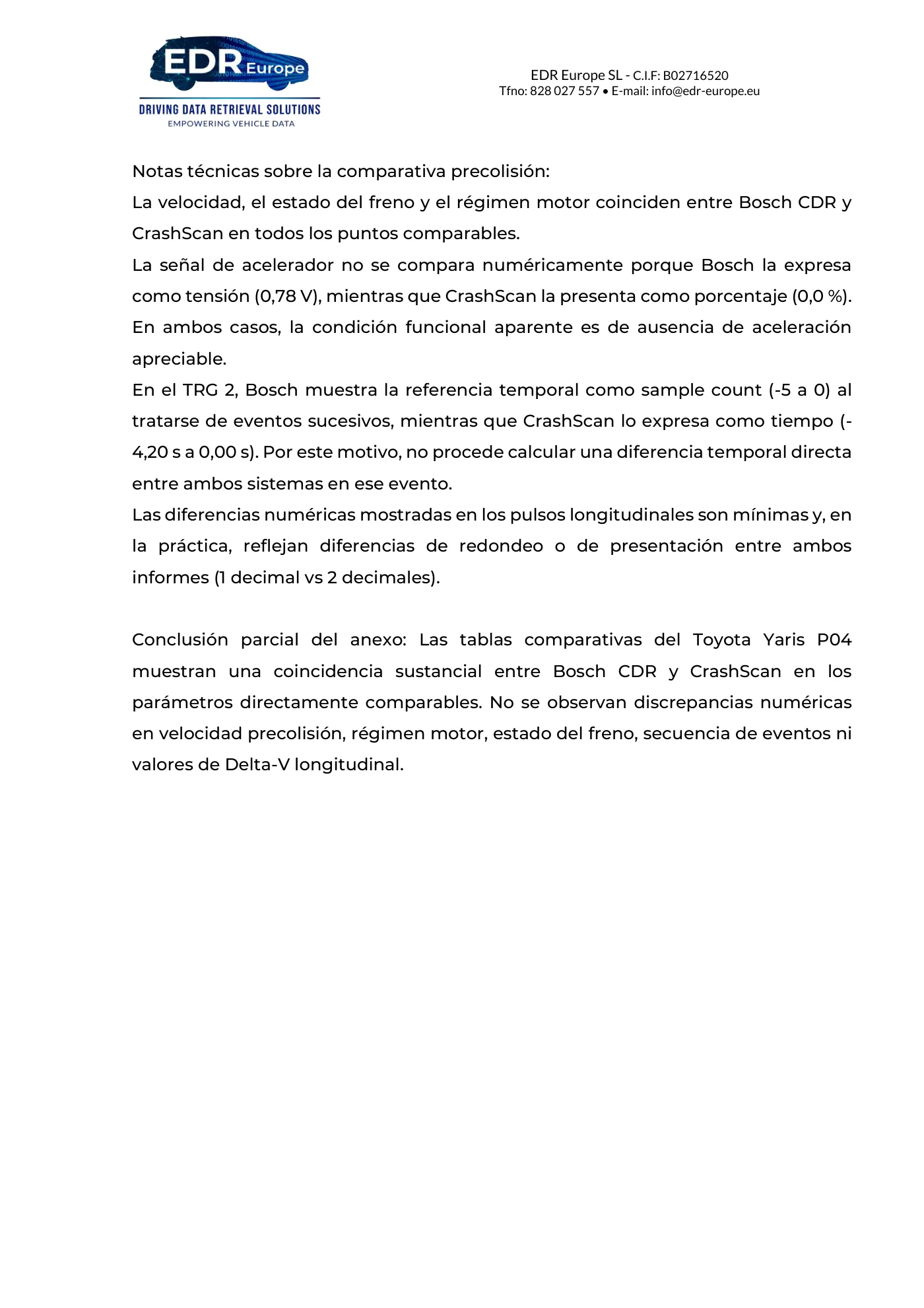
Read page 90 text
EDR Europe SL - C.I.F: B02716520 Tfno: 828 027 557 • E-mail: info@edr-europe.eu Notas técnicas sobre la comparativa precolisión: La velocidad, el estado del freno y el régimen motor coinciden entre Bosch CDR y CrashScan en todos los puntos comparables. La señal de acelerador no se compara numéricamente porque Bosch la expresa como tensión (0,78 V), mientras que CrashScan la presenta como porcentaje (0,0 %). En ambos casos, la condición funcional aparente es de ausencia de aceleración apreciable. En el TRG 2, Bosch muestra la referencia temporal como sample count (-5 a 0) al tratarse de eventos sucesivos, mientras que CrashScan lo expresa como tiempo (- 4,20 s a 0,00 s). Por este motivo, no procede calcular una diferencia temporal directa entre ambos sistemas en ese evento. Las diferencias numéricas mostradas en los pulsos longitudinales son mínimas y, en la práctica, reflejan diferencias de redondeo o de presentación entre ambos informes (1 decimal vs 2 decimales). Conclusión parcial del anexo: Las tablas comparativas del Toyota Yaris P04 muestran una coincidencia sustancial entre Bosch CDR y CrashScan en los parámetros directamente comparables. No se observan discrepancias numéricas en velocidad precolisión, régimen motor, estado del freno, secuencia de eventos ni valores de Delta-V longitudinal.
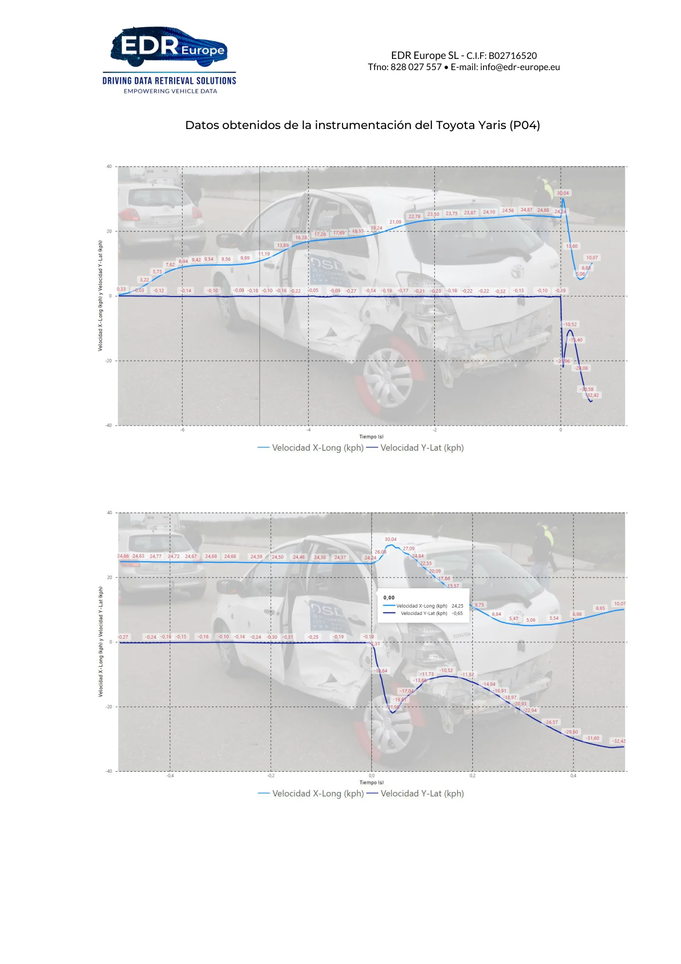
Read page 91 text
EDR Europe SL - C.I.F: B02716520 Tfno: 828 027 557 • E-mail: info@edr-europe.eu Datos obtenidos de la instrumentación del Toyota Yaris (P04)
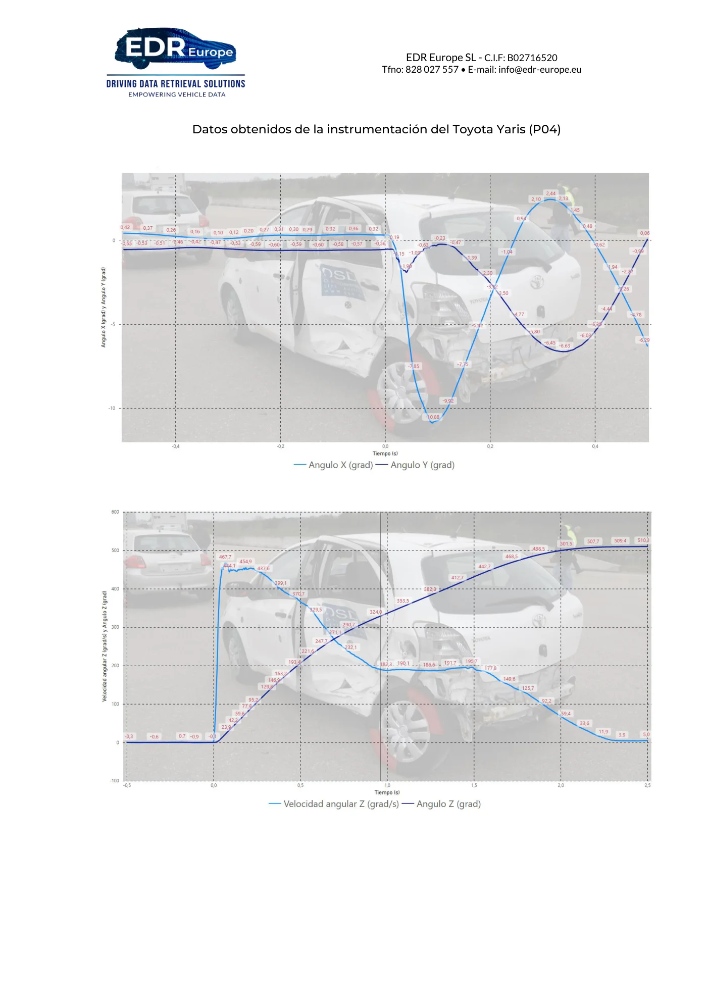
Read page 92 text
EDR Europe SL - C.I.F: B02716520 Tfno: 828 027 557 • E-mail: info@edr-europe.eu Datos obtenidos de la instrumentación del Toyota Yaris (P04)
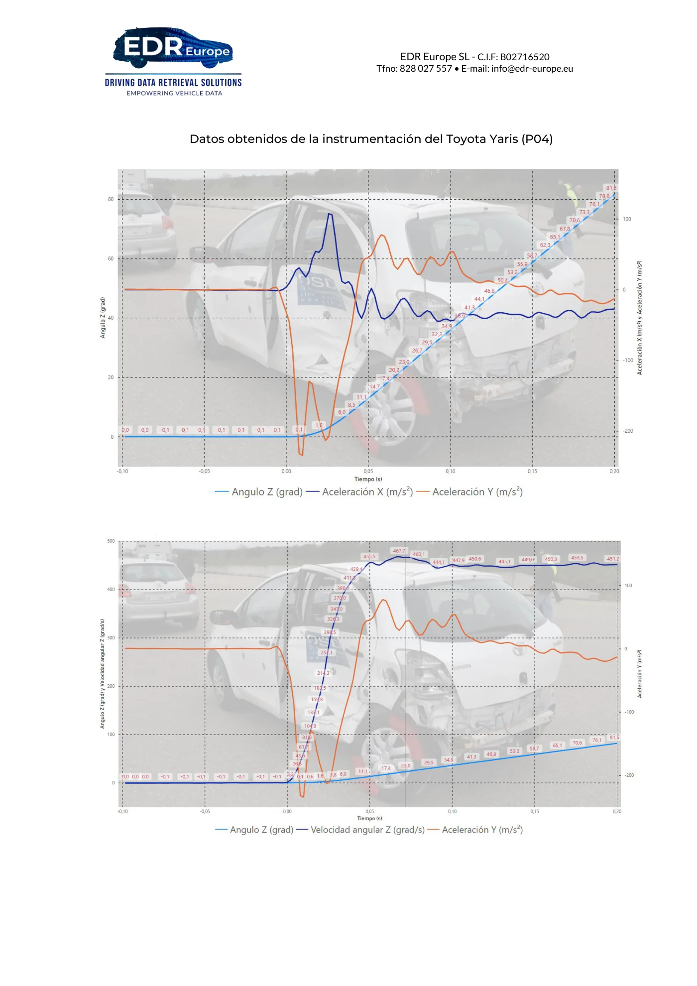
Read page 93 text
EDR Europe SL - C.I.F: B02716520 Tfno: 828 027 557 • E-mail: info@edr-europe.eu Datos obtenidos de la instrumentación del Toyota Yaris (P04)